00192809-01 - 第62页
6 Set-up mode User M anual V 1.15 - Productivity Lift 6.2 Machine type Sof tware vers ion V 40.1 1 Edition 01/2001 54 Convert 4 → 2 : Convert m odule from 4 tracks to 2 tracks, w hereb y 4 t racks in dica te the lower an…
User Manual V 1.15 - Productivity Lift 6 Set-up mode
Software version V 40.11 Edition 01/2001 6.2 Machine type
53
Cluster module : The intermediate module is located after the input module and is defined as
the intermediate module as long as the subsequent placement machines are
of the same type. The intermediate module accepts either assembled PCBs
from tracks 1, 2 and 4, and transfers them further on track 4, or it accepts
unassembled PCBs from track 3 and attempts to deposit them at the follow-
ing placement machine. If the following placement machine is occupied, the
unassembled PCBs are transported further via track 3 to the next lift or
placement machine.
$OORFDWLRQRIWKHLQOHWVDQGRXWOHWVWRHDFKRWKHU
1. take-over inlet track 1 → hand-over outlet track 4
2. take-over inlet track 2 → hand-over outlet track 4
3. take-over inlet track 3 → hand-over outlet track 1, 2 or 3
4. take-over inlet track 4 → hand-over outlet track 4
In order to prevent the system becoming blocked, only one PCB may be
transferred if the allocated outlet is ready. Fixed priorities are allocated to the
individual transport directions. Inlet tracks 1 and 2 as well as outlet tracks 1
and 2 all have the same priority.
2WKHUZLVHWKHIROORZLQJDSSOLHV
1. take-over inlet track 3 → hand-over outlet tracks 1 and 2
2. take-over inlet tracks 1 and 2 → hand-over outlet track 4
3. take-over inlet track 3 →hand-over outlet track 3
4. take-over inlet track 4 → hand-over outlet track 4
Cross module : The setting "cross module" must always be selected if the type of placement
machine changes in the line. The cross module handles all incoming PCBs
as if they are unassembled. In this way, the PCBs arriving on tracks 1, 2 and
4 are presented to the placement machine for processing. If the following
placement machine is of the same type, PCBs can also be transferred on
track 3 at the cross module if the current placement machine is occupied. If
the cross module is the last lift before the final module, no PCBs may be
transferred on track 3. Similarly, no PCBs may be accepted from the last in-
termediate module before this cross module.
6 Set-up mode User Manual V 1.15 - Productivity Lift
6.2 Machine type Software version V 40.11 Edition 01/2001
54
Convert 4 → 2 : Convert module from 4 tracks to 2 tracks, whereby 4 tracks indicate the lower
and upper two tracks.
$SSOLFDWLRQ
A suitable device should be used to break up a long placement line to allow
access for people, for example. This reduces the transport tracks to 2 tracks,
since a device can not have two tracks on the lower transport level. With the
convert module 4→2, PCB transport is reduced to 2 tracks, separated ac-
cording to assembled and unassembled PCBs.
Convert 2 → 4 : Convert module from 4 tracks to 2 tracks, whereby 4 tracks indicate the lower
and upper two tracks.
$SSOLFDWLRQ
A suitable device should be used to break up a long placement line to allow
access for people, for example. This reduces the transport tracks to 2 tracks,
since a device can not have two tracks on the lower transport level. With the
convert module 2→4, PCB transport is increased again to 4 tracks, sepa-
rated according to assembled and unassembled PCBs, following this type of
interruption.
Output module : The final module is defined as the last lift in the direction of transit, after the
Siplace systems. Essentially, the final module has no lower belt. If the lift is
implemented as the final module, the above mentioned system types can not
be selected. The PCBs are transferred from tracks 1, 2 and 4. Transfer to
tracks 1 and 2 has priority. The printed circuit boards can only be delivered
at the final module via outlet tracks 1 and 2. No PCBs can be transferred from
track 3 or transported further on this track.
Machine type
Input module
User Manual V 1.15 - Productivity Lift 6 Set-up mode
Software version V 40.11 Edition 01/2001 6.3 Ramp up mode / Ramp down mode
55
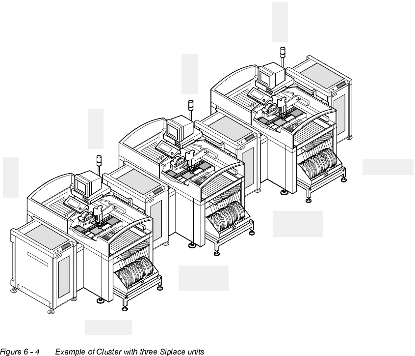
5DPSXSPRGH5DPSGRZQPRGH
([DPSOHRI&OXVWHUZLWKWKUHH6LSODFHXQLWV
E
i
n
g
a
n
g
s
m
o
d
u
l
I
n
p
u
t
m
o
d
u
l
e
Belademodus 1:2
Ramp up mode 1:2
Z
w
i
s
c
h
e
n
m
o
d
u
l
C
l
u
s
t
e
r
m
o
d
u
l
e
Z
w
i
s
c
h
e
n
m
o
d
u
l
C
l
u
s
t
e
r
m
o
d
u
l
e
E
n
d
m
o
d
u
l
O
u
t
p
u
t
m
o
d
u
l
e
Belademodus 1:1
Entlademodus 1:0
Ramp up mode 1:1
Ramp down mode 1:0
Belademodus 1:0
Entlademodus 1:1
Ramp up mode 1:0
Ramp down mode 1:1
Entlademodus 1:2
Ramp down mode 1:2