00192809-01 - 第66页
6 Set-up mode User M anual V 1.15 - Productivity Lift 6.5 PCB take over Software version V 40. 1 1 Edition 01/2001 58 3 &%W DNHRYHU The pos sibilit y of de fining the setti ng for PCB takeove r at the i nlet of…
User Manual V 1.15 - Productivity Lift 6 Set-up mode
Software version V 40.11 Edition 01/2001 6.4 Underneath buffer
57
$YDLODELOLW\RI5DPSXS5DPSGRZQPRGHGHSHQGLQJRQPDFKLQHW\SH
The ramp up, ramp down mode depends on the selected machine type as defined in the table be-
low.
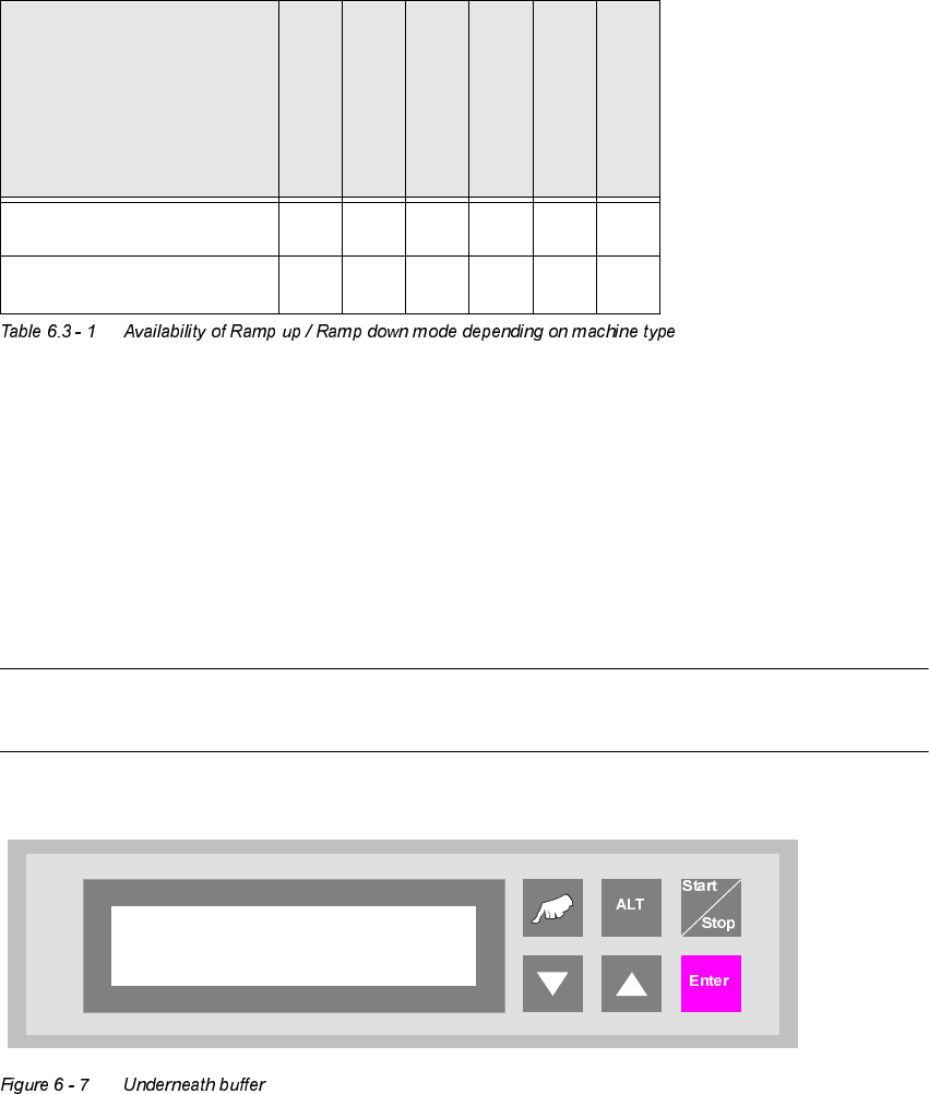
8QGHUQHDWKEXIIHU
The lower belts can be used as so-called underfloor buffers. This means that if the function is
switched on, two PCBs could be transferred on the belt. As a result, there is an additional further
storage space available for each belt.
127(
This menu is not displayed if the underfloor conveyor is switched off (see 5.8).
,QSXWPRGXOH
&OXVWHUPRGXOH
&URVVPRGXOH
&RQYHUW
&RQYHUW
2XWSXWPRGXOH
5DPSXSPRGH
;;;;
5DPSGRZQPRGH
;; ;;
Underneath buffer
Turned off
6 Set-up mode User Manual V 1.15 - Productivity Lift
6.5 PCB take over Software version V 40.11 Edition 01/2001
58
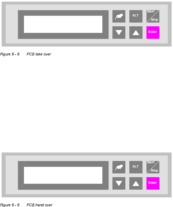
3&%WDNHRYHU
The possibility of defining the setting for PCB takeover at the inlet of the upper transport level. The
following settings are possible:
Double track : Depending on the request signals, PCBs are taken at the inlet alternately
from track 1 and track 2.
Track 1 : PCBs are taken from track 1 only
Track 2 : PCBs are taken from track 2 only.
3&%KDQGRYHU
The possibility of defining the setting for PCB hand over at the outlet of the upper transport level.
The following settings are possible:
Double track : Depending on the request signals, PCBs are taken at the inlet alternately
from track 1 and track 2.
Track 1 : PCBs are taken from track 1 only.
Track 2 : PCBs are taken from track 2 only.
PCB take over
Double track
PCB hand over
Double track
User Manual V 1.15 - Productivity Lift 6 Set-up mode
Software version V 40.11 Edition 01/2001 6.7 Pass through
59
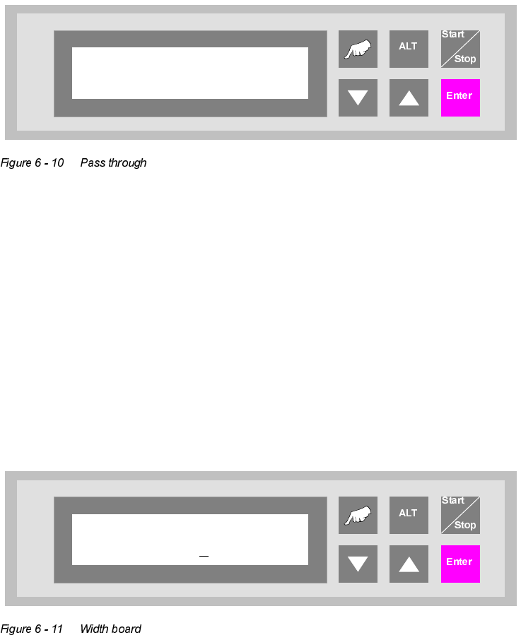
3DVVWKURXJK
If this function is turned on, PCBs are only taken at the upper inlet track 1 or 2 and only delivered
again at the corresponding upper outlet. This is implemented by the additional top conveyor mod-
ule, which is lowered pneumatically to the transport level. This also serves to turn off the shuttle.
:LGWKERDUG
This menu item is only active if the settings "automatic" or "only at start" were selected in the chap-
ter "Width adjusting".
The value to be entered here can be used to prescribe the transport width of the system numeri-
cally as an absolute value. After starting the automatic operating mode, and after each width ad-
justment reference run, the width prescribed here is automatically reset.
The unit of value is [0.1 mm] in a setting range of 500 to maximum width (corresponds to 50 mm
to maximum width).
Pass through
Turned off
Width board
2000