00192809-01 - 第74页
7 Manual mode User M anual V 1.15 - Productivity Lift 7.6 Manual mode 7 - Width belts Software version V 40. 1 1 Edit ion 01/2001 66 0DQ XDOPRG H : LG WKE HOW V Functio n to set the width for the under floor c…
User Manual V 1.15 - Productivity Lift 7 Manual mode
Software version V 40.11 Edition 01/2001 7.4 Manual mode 4 - Underneath belt
65
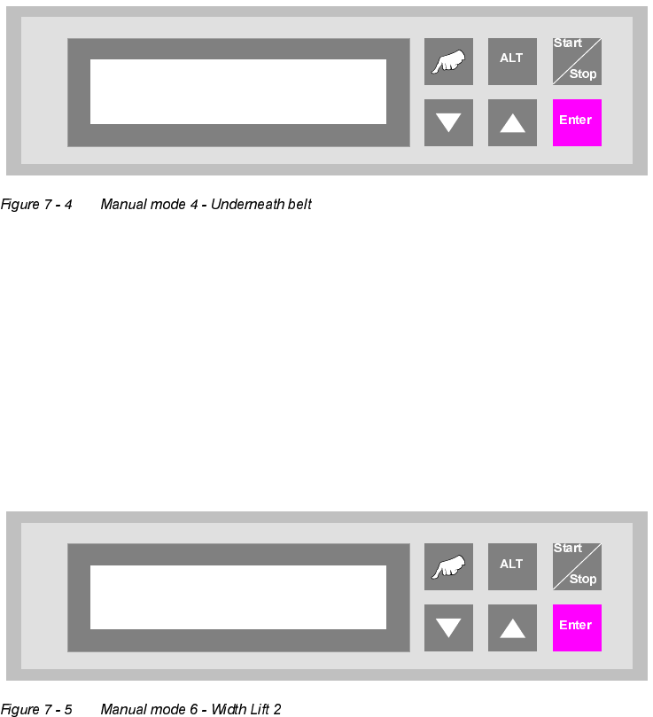
0DQXDOPRGH8QGHUQHDWKEHOW
Test function for the underfloor conveyor.
The cursor key "▲" can be used to switch on the drive of the first segment (inlet) and the "▼" key
to switch on that of the second segment (outlet).
The "Enter" key can be used to proceed to the next test function. To cancel the procedure, exit
the menu using the "Start/Stop" key.
0DQXDOPRGH:LGWK/LIW
Function to set the width for the shuttle.
The cursor keys "▲" and "▼" can be used to increase and/or decrease the width of the conveyor.
The "Enter" key can be used to proceed to the next test function. To cancel the procedure, exit
the menu using the "Start/Stop" key.
Manual mode 4
Underneath belt
Manual mode 6
Width Lift 2
7 Manual mode User Manual V 1.15 - Productivity Lift
7.6 Manual mode 7 - Width belts Software version V 40.11 Edition 01/2001
66
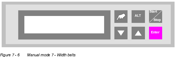
0DQXDOPRGH:LGWKEHOWV
Function to set the width for the underfloor conveyor.
The cursor keys "▲" and "▼" can be used to increase and/or decrease the width of the conveyor.
The "Enter" key can be used to return to the first test function. To cancel the procedure, exit the
menu using the "Start/Stop" key.
Manual mode7
Width belts
User Manual V 1.15 - Productivity Lift 8 Automatic tracking
Software version V 40.11 Edition 01/2001 8.1 Automatic tracking via hybrid light barriers
67
$XWRPDWLFWUDFNLQJ
The Productivity Lift can be fitted with two types of automatic tracking.
1. Tracking via hybrid light barriers
2. Tracking via CAN bus
$XWRPDWLFWUDFNLQJYLDK\EULGOLJKWEDUULHUV
The system is equipped with an automatic tracking facility for the transport width.
In the automatic operating mode, the transport width is tracked automatically. Built-in hybrid light
barriers detect the position of the mobile transport cheek of the previous or following device and
automatically adapt the transport width of the lift. The sensor mechanism detects the direction in
which adjustment is made and proceeds accordingly. If signals overlap, a reference run is per-
formed. In this case, the width setting is increased to the maximum width and then the transport
width is reset.
$XWRPDWLFWUDFNLQJYLD&$1%XV
The lift is connected to other systems via a CAN bus. The data for the current width are transferred
via this CAN bus. The configuration of the lift determines which system is responsible for the width
and how the width is queried and checked.
Communication via CAN bus is only possible with our systems.