SIPLACE D1 规格说明书英文版 - 第11页
11 Placement Heads Standard Functions / Options 12 nozzle Collect & Place head 6 nozzle Co llect & Pla ce head S tandard- functions Camera, va cuum sensor , f orce measurement, PCB warpage, check, individual reco…
10
Head Modularity
Overview
The SIPLACE D1 is charac-
terized by maximum flexibil-
ity in the production process.
This flexibility is partly due to
the head modularity of the
placement machine as it
allows different placement
head variants to be config-
ured to suit the production
requirements. The gantry on
the SIPLACE D1 can be
equipped with one (as a
SIPLACE D1S) or two
(SIPLACE D1) placement
heads, as required. The fol-
lowing placement head con-
figurations are possible:
Operation with two place-
ment heads:
• C&P12 and P&P head
• C&P6 and P&P head
Operation with just one
placement head:
• C&P12 head
• C&P6 head
• P&P head
If the placement system was
delivered with just one place-
ment head, you can retrofit a
second placement head
using an upgrade kit.
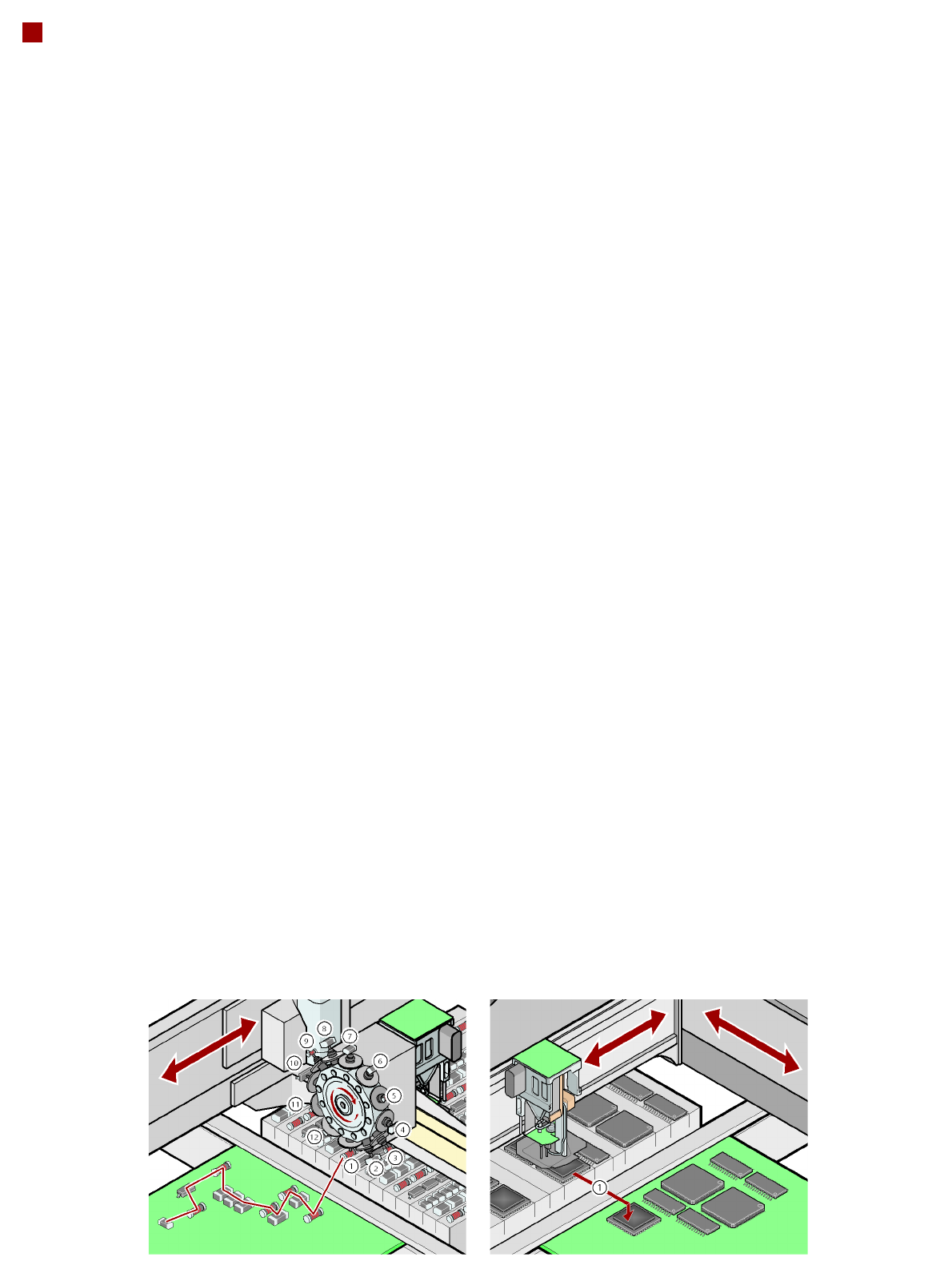
Collect&Place principle
The SIPLACE 12 and 6-
nozzle Collect&Place heads
work on the Collect&Place
principle. This means that,
within each cycle, 12 or 6
components are picked up
and "collected" by the place-
ment head, are optically cen-
tered on the way to the board
and are rotated into the
required placement angle.
They are then placed gently
and accurately on the PCB.
This principle is particularly
suitable for the high-speed
placement of standard com-
ponents.
Pick&Place principle
The Pick&Place head on the
SIPLACE D1 first picks up
the component. On the way
to the placement position, it
centers it optically and
rotates is into the required
placement angle. This
method is particularly suit-
able for fast and accurate
placement of special compo-
nents in the fine-pitch and
super-fine pitch ranges.
Checking and self-learning
functions
The SIPLACE placement
heads' reliability can be fur-
ther increased with various
checking and self-learning
functions.
• Component sensor
It checks for the presence
of a component at the
nozzle before and after the
pick-up and placement
process.
• Digital camera on the
placement head
Checks the position of
each component at the
nozzle. Any deviations
from the required pick-up
position are corrected
before placement takes
place.
• Force sensor
Monitors the specified
component set-down
forces. With the sensor
stop method, differences
in height during pick-up
and any unevenness of
the PCB surface are com-
pensated during place-
ment.
• Vacuum sensor
Checks whether the com-
ponent was picked up or
set down correctly.
Collect&Place principle Pick&Place principle
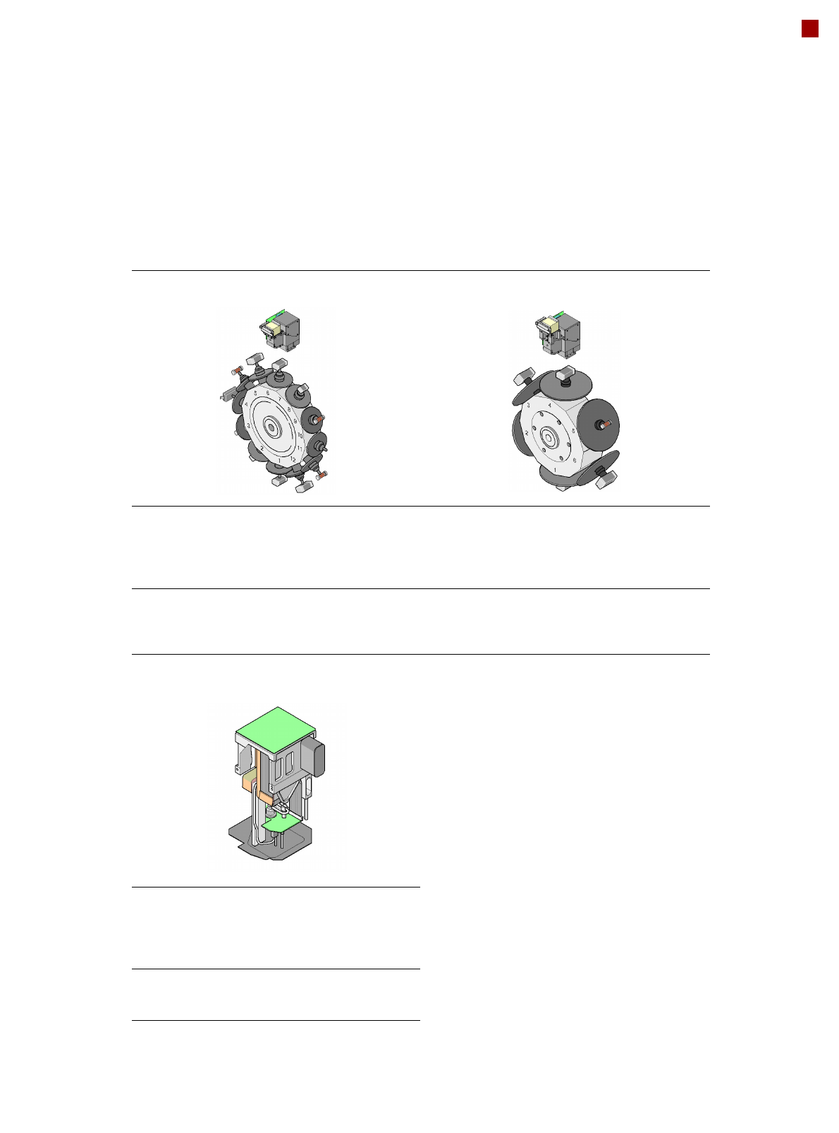
11
Placement Heads
Standard Functions / Options
12 nozzle Collect &Place head 6 nozzle Collect&Place head
Standard-
functions
Camera, vacuum sensor, force
measurement, PCB warpage,
check, individual recording for
each component
Standard
functions
High-resolution camera,
vacuum sensor, force measure-
ment, PCB warpage, check,
individual recording for each
component
Options High-resolution camera, compo-
nent sensor, short nozzle, short
sleeve, nozzle changers, special
nozzles
Options Short nozzle, short sleeve,
nozzle changers, special
nozzles
Pick&Place head
Standard
functions
Fine-pitch camera, vacuum sen-
sor, force sensor, nozzle
changer, PCB warpage check,
individual recording for each
component
Options Flip-chip camera, special
nozzles, grippers, coplanarity
module
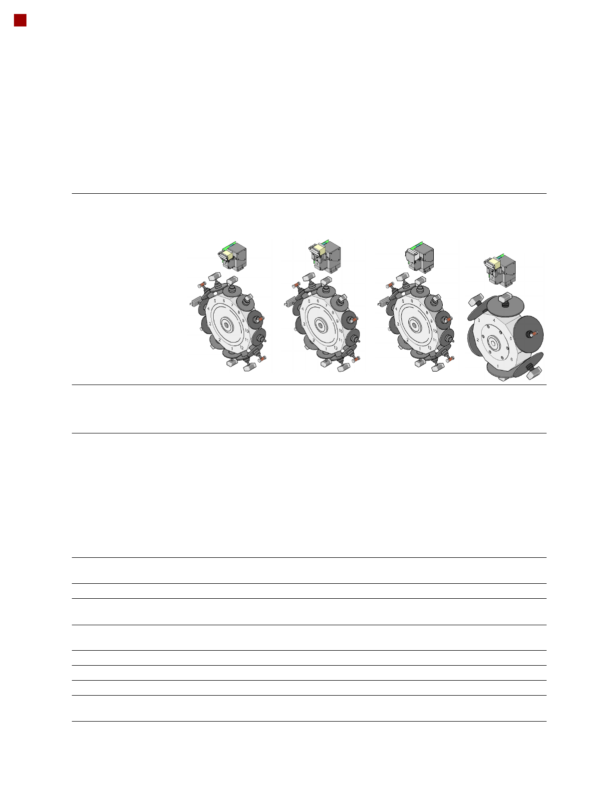
12
Placement Heads
Collect&Place Heads
12-nozzle
Collect&Place head
CO camera type 28
12-nozzle
Collect&Place head
CO camera type 29
12-nozzle
Collect&Place head
CO camera type 38
6-nozzle
Collect&Place
head
CO camera type 29
Component range
a
a) Please note that the range of components that can be placed is also affected by the pad geometry, customer-specific
standards, component packaging tolerances and component tolerances
0402 to PLCC44,
BGA, µBGA, flip-
chip, TSOP, QFP, SO
to SO32, DRAM
0201
b
to flip-chip, bare
die, PLCC44, BGA,
µBGA, TSOP, QFP,
SO to SO32, DRAM
b) With 0201 package
01005
c
to 16 x
16 mm²
c) With 01005 package
0201to 27 x
27 mm²
Component specification
max. height
min. lead pitch
min. lead width
min. ball pitch
min. ball diameter
min. dimensions
max. dimensions
max. weight
6 mm
0.5 mm
0.2 mm
0.35 mm
0.2 mm
1.0 x 0.5 mm²
18.7 x 18.7 mm²
2 g
6 mm
0.3 mm
0.15 mm
0.25 mm
0.14 mm
0.6 x 0.3 mm²
b
18.7 x 18.7 mm²
2 g
6 mm
0.25 mm
0.1 mm
0.25 mm
0.14 mm
0.4 x 0.2 mm²
16 x 16 mm²
2 g
8.5 mm
0.3 mm
0.15 mm
0.25 mm
d
0.35 mm
e
0.14 mm
d
0.2 mm
e
0.6 x 0.3 mm²
27 x 27 mm²
5 g
d) For components < 18 x 18 mm²
e) For components 18 x 18 mm²
Programmable set-down
force
2.4 N - 5.0 N 2.4 N - 5.0 N 2.4 N - 5.0 N 2.4 N - 5.0 N
Nozzle types 9xx 9xx 9xx 8xx, 9xx
X/Y accuracy
f
f) The accuracy value was measured using the vendor-neutral IPC standard
± 50 µm/3
± 67 µm/4
± 50 µm/3
± 67 µm/4
± 50 µm/3
± 67 µm/4
± 52.5 µm/3
± 70 µm/4
Angular accuracy ± 0.53°/3
± 0.71°/4
± 0.53°/3
± 0.71°/4
± 0.53°/3
± 0.71°/4
± 0.225°/3
± 0.3°/4
Component range 98% 98.5% 96% 99.8%
Component camera type 28 29 38 29
Illumination levels 5 5 5 5
Possible illumination level
settings
256
5
256
5
256
5
256
5