ThermoFlex-Manual.pdf - 第105页
Section 8 ThermoFlex 8-3 Thermo Scientific W etted Materials P 1, P 2, MD 1 and MD 2 Pumps 300 Series Stainless Steel Bronze Carbon Graphite Ceramic Fluorocarbon (Viton ® ) P olysulfone T ank P olyeth ylene Brass EPDM Pyr…
Section 8
8-2 ThermoFlex
Thermo Scientific
Water-Cooled
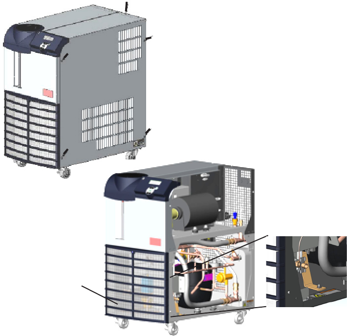
Draining ThermoFlex1400 - 2500 water-cooled chillers is accomplished by
removing the right side panel. Use a Phillips head screwdriver to remove
the ve screws indicated in the illustration below. Slide the panel back
approximately one inch, then lift slightly from the rear to disengage the
panel's two tabs from their slots.
Petcock Valve
The drain for ThermoFlex3500 and 5000 is
located behind the condenser filter.
The drain for ThermoFlex7500 and 10000
is located behind the access panel on the
lower left front of the chiller. The panel has
two ¼ turn fasteners (cross head).
The drain for Thermoflex15000 - 24000 is a
¼" plug located on the rear of the chiller.
Figure 8-2 Water-Cooled
Install a
7
/
16
" ID tube on the drain petcock valve located on the lower end
of the exchanger. Open the valve to allow uid to drain into an external
device. When draining is complete close the valve and replace the panel.
A wet-vac is needed on the facility water inlet connection to thoroughly
drain any remaining uid from the lines.
Section 8
ThermoFlex 8-3
Thermo Scientific
Wetted Materials
P 1, P 2, MD 1 and MD 2 Pumps
300 Series Stainless Steel
Bronze
Carbon Graphite
Ceramic
Fluorocarbon (Viton
®
)
Polysulfone
Tank
Polyethylene
Brass
EPDM
Pyrex
®
Plumbing
300 Series Stainless Steel
Bronze
Fluorocarbon (Viton
®
)
Nickel
Polypropylene
EPDM
Brass
Copper
Teon
®
PPS (ow transducer)
Nitrile (Buna-n
®
)
Riton
®
(optional drain tting)
Viton® (optional drain tting o-rings)
Filter bag
Polypropylene
Mono-lament nylon
Cap and Funnel
Acetal Copolymer
P 3, P 4 and P 5 Pumps
316 Series Stainless Steel
Carbon
Silicon Carbide
Fluorocarbon (Viton
®
)
T 0 and T 1 Pumps
Stainless Steel AISI 304
Bronze ASTM B62
Bronze ASTM B16
Buna N
Buna/Ceramic
Buna/Carbon
T 5 Pumps
Stainless Steel AISI 304
Bronze w/monel
Carbon
Buna N
Ceramic
Buna/Carbon
Section 8
8-4 ThermoFlex
Thermo Scientific
Internal Fluid
Temperature Sensor
(rdt1) Calibration
The ThermoFlex has been designed to minimize the need for calibration.
However, if calibration is desired or recommended by our Sales, Service and
Customer Support, please use the following procedure.
This procedure requires a running chiller and a calibrated reference
thermometer.
Note Uninsulated applications may cause the internal temperature and
an external reference temperature to differ and to uctuate. If inaccurate
calibration is suspected, place the reference thermometer as close to the
ThermoFlex process outlet as possible.
Note If it is more convenient, perform the low-end calibration before doing
the high-end.
Do not pick calibration points that are outside the safe operating limits of the
uid in your application. For example with water, 40°C and 5°C are typical
high and low calibration points.
Run the temperature to a suitable high-end calibration point. Place a
calibrated reference thermometer in the reservoir. Ensure the uid
temperature is stabilized.
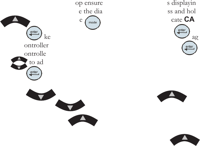
To enter the Calibration Loop ensure the controller display is displaying the
process uid temperature, see the diagram on next page. Press and hold the
and then press the key. The display will indicate CAL.
Press the key and the controller will display rtd1. Press again
and the controller will display r1 H (high-end calibration). Press again
and the controller will ash between r1 H and the temperature.
Use to adjust the temperature to match the reference thermometer.
Press the key again to accept the value.
Press the key until StorE is displayed, press to save
the new value, press to not save it.
Note After pressing the button at the StorE prompt wait several
seconds before proceeding to ensure that a bad calibration message (Er 16)
does not appear. Premature use of the keypad after pressing may
cancel the bad calibration error message.
Run the temperature to a suitable low-end calibration point. At the r1 L (low-
end calibration) display repeat the procedure.