ThermoFlex-Manual.pdf - 第119页
Thermo Scientific Appendix C ThermoFlex C-3 Thermo Scientific • rELA Y is used to congure relay 1 ( CodE 1 ) and relay 2 ( CodE 2 ), see T ables 1 and 2 on the next pag e. F or example: T o have just the drip pan, 4, and …
Thermo Scientific
C-2 ThermoFlex
Appendix C
Thermo Scientific
Thermo Scientific
PIN NAME NOTES DEFINITION
13 REMOTE SETPOINT Note 3 Connect to pin 1 to allow the setpoint to be changed remotely through pin 15
ENABLE REMOTE SETPOINT.
14 REMOTE START Note 3 Connect to pin 1 to turn chiller on. Disconnect to turn chiller off.
Note: Pins 1 and 12 must be connected to allow operation from this pin.
15 REMOTE SETPOINT Note 2, 4 Analog Voltage Input 0-10VDC, 10mV/°C, or 4-20mA: Reference to pin 6.
Apply a DC voltage to this pin to adjust the chiller's setpoint:
Default Range = 0 – 10V (where: 0V = Low Temp Span, 10V = Hi Temp Span)
(Input Impedance > 600K)
Optional Range = 10mV/
O
C. (Ex: 200mV = 20°C) (Max Input Voltage = 10VDC,
or 4-20mA, 4mA = low temp span, 20 mA = high temp span.
Note 1: All relay contacts (except for Pin 10) are normally OPEN when power is off. Pin 10 contacts are normally CLOSED when power is off.
Relay contacts are rated: 24V AC/DC, 2A, <= 0.08 Ohm maximum each or 5A total for all relays combined, 1mA minimum, switching capacity:
48VA/48W (Resistive load only).
Note 2: Default = 0-10VDC
Note 3: Connect to digital ground (pin 1) using a low resistance connection (gold contact relay).
Note 4: Remote setpoint must be enabled, pin 13
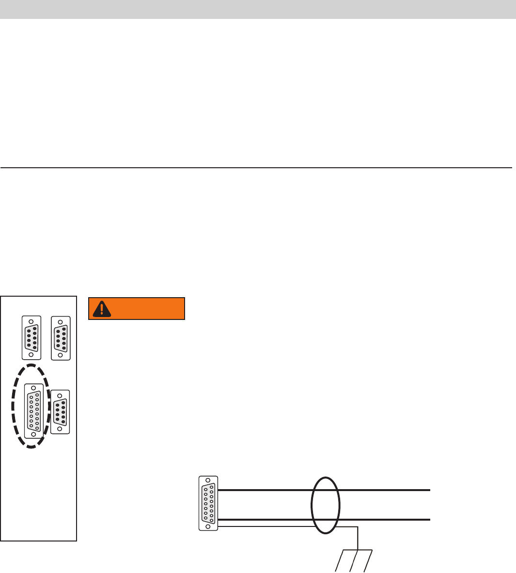
Figure C-1 Analog I/0 Connector
When making your connection to the ThermoFlex Analog I/0
connector, in order to comply with the EMC directive:
• Use a shielded I/0 cable
• Connect the remote end of the cable shield to earth ground.
• Connect cable shield to ThermoFlex end connector.
A I/0 15-pin D-sub
15 conductor cable with shield
Connect shield to earth ground
Connect shield to ThermoFlex connector
1 2 3 4 5
6 7 8 9
1 2 3 4 5
6 7 8 9
1 2 3 4 5
6 7 8 9
8 7 6 5 4 3 2 1
15 14 13 12 11 10 9
RS232 RS485
A I/O REMOTE
SENSOR
8 7 6 5 4 3 2 1
15 14 13 12 11 10 9
Never apply line voltage to any of the connections.
WARNING
Thermo Scientific
Appendix C
ThermoFlex C-3
Thermo Scientific
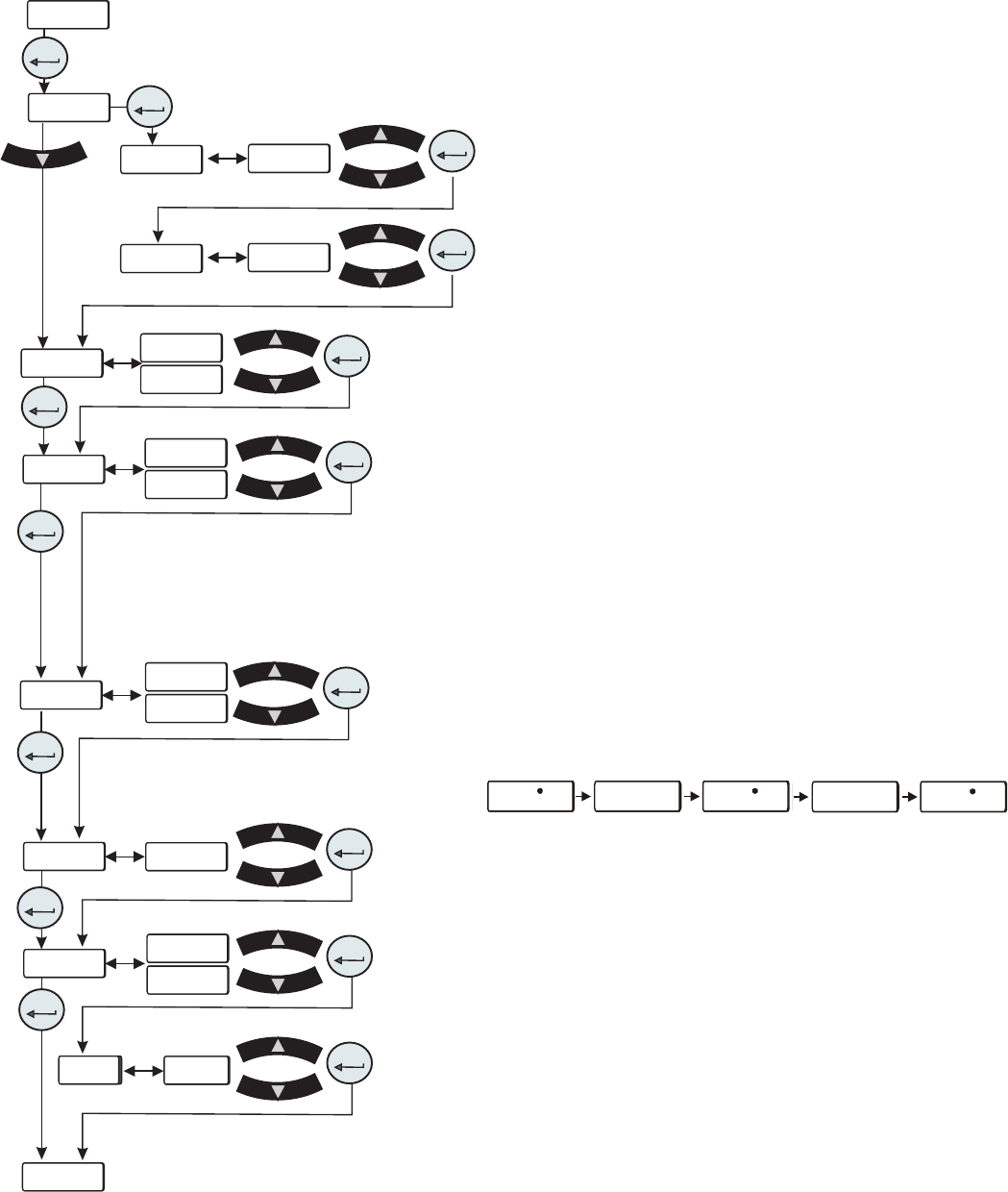
• rELAY is used to congure relay 1 (CodE 1) and
relay 2 (
CodE 2), see Tables 1 and 2 on the next page.
For example: To have just the drip pan, 4, and low
temp, 8, error faults enabled for relay 1 you would
enter their sum, 12, at the
CodE 1 display. To have the
tank overow, 2, the low temp, 16, and high pressure,
1024, error faults enabled for relay 2 you would enter
their sum, 1040, at the
CodE 2 display.
This display depends on your chiller
configuration, see Section 4.
Figure C-2 Analog I/0 Loop
xx. x Cxx. x C xx. x C
xx. x Cxx. x C xx. x C
• r rtd is used to enable/disable the remote temperature
sensor. See Table 3 for pin out information.
Note There is no other indication on the chiller that the
remote sensor is enabled.
• r.Start is used to enable/disable the remote start/stop.
Note Enabling analog I/O remote start/stop disables
the chiller’s local controller start/stop capability. Enabling
analog I/O remote also overrides serial communications
start/stop commands.
• r SEt is used to enable/disable the remote setpoint.
Note When remote setpoint is enabled a ashing dot will
appear on the controller's display as shown below.
• AnAin is used to congure the analog voltage input type.
Type 1: 0 - 10 VDC (Default)
Type 2: 10 mV/°C
Type 3: 4 - 20 mA
• dAC is used to enable/disable the digital to analog
converter. Once enabled, the desired output type can be
selected.
Note The Type display only appears if dAC is set to on.
Type 1: 0 - 10 VDC (Default)
Type 2: 10 mV/°C
Type 3: 4 - 20 mA
rELAY
CodE 1
CodE 2
enter
enter
xx
xx
xxxxx
xxxxx
enter
enter
r rtd
r.Start
r SEt
AnAin
dAC
dAC
----
xx
xx
xx
xx
xx
xx
xx
xx
xx
xx
OFF
OFF
OFF
OFF
on
on
on
on
tYPE1
tYPE1
enter
enter
enter
enter
enter
enter
enter
enter
enter
enter
enter
OPt

Thermo Scientific
C-4 ThermoFlex
Appendix C
Thermo Scientific
Thermo Scientific
Table 1 Configurable Relay #1 (CodE1)
Error Error Code Factory Default
Low Level (option) LLF Enable 1 (Default)
Tank Overflow o FLo Disable 2
Drip Pan Full (option) driP Disable 4
Low Temp Lo t* Disable 8
High Temp Hi t* Disable 16
Low Flow (option) LoFLo* Enable 32 (Default)
High Flow (option) HiFLo* Disable 64
Low Resistivity (option) Er 28* Disable 128
High Resistivity (option) Er 30* Disable 256
High Pressure Hi P1* Disable 512
Low Pressure Lo P1* Disable 1024
Chiller Fault Any Fault Enable 2048 (Default)
Pump/Chiller Shut Off Status bit(s) Disable 4096
Refrigeration Shut Off Status Bit Disable 8192
Limit Fault (option) PHEr, oL, LPC, HPC, Er 47, Er 48 Enable 16384 (Default)
Sensor Fault Er 23, Er 24, Er 25, Er 26 Disable 32768
external sensor opened or shorted Default Relay Code 1 Display = 18465
(1 + 32 + 2048 + 16384 = 18465)
*Regardless of alarm setting - fault or indicator
Table 2 Configurable Relay #2 (CodE2)
Error Error Code Factory Default
Low Level (option) Add Disable 1
Tank Overflow o FLo Disable 2
Drip Pan Full (option) driP Disable 4
Auto Refill Error (option) rEFiL Disable 8
Low Temp Lo t* Enable 16 (Default)
High Temp Hi t* Enable 32 (Default)
Low Flow (option) Lo FL* Disable 64
High Flow (option) Hi FL* Disable 128
Low Resistivity (option) Er 28* Disable 256
High Resistivity (option) Er 30* Enable 512 (Default)
High Pressure Hi P1* Disable 1024
Low Pressure Lo P1* Disable 2048
Indicator (warning) Any Indicator Disable 4096
PM Timer (option) di, SEr 1 to 6 Disable 8192
Communication Error Er 15, Er 41, Er 42 Disable 16384
Sensor Fault Er 23, Er 24, Er 25, Er 26 Enable 32768 (Default)
external sensor opened or shorted Default Relay Code 2 Display = 33328
(16 + 32 + 512 + 32768 = 33328)
*Regardless of alarm setting - fault or indicator