ThermoFlex-Manual.pdf - 第122页
Thermo Scientific C-6 ThermoFlex Appendix C Thermo Scientific Thermo Scientific xx.x xx.x 9.50 4.50 Ao Hi Ao Lo xx.x C mode rtd1 Flo CAL enter enter enter enter mode r rtd A in Aout1 StorE PrES1 The analog output uses a 2-p…
Thermo Scientific
Appendix C
ThermoFlex C-5
Thermo Scientific
Analog Input Calibration
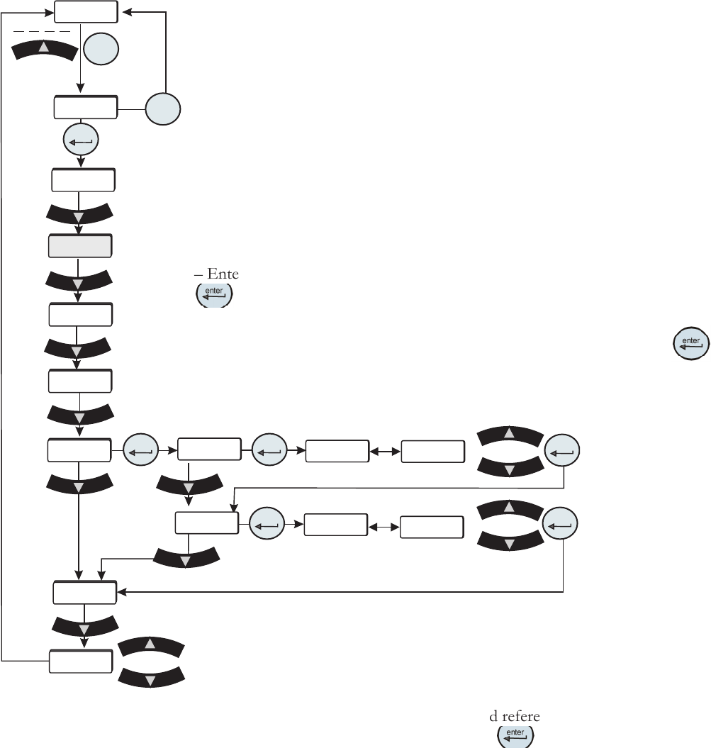
Figure C-3 Analog Input
Calibration Loop
xx.x
xx.x
9.50
0.50
Ai Hi
Ai Hi
Ai Lo
Ai Lo
xx.x C
mode
rtd1
Flo
CAL
enter
enter
enter
enter
enter
enter
mode
r rtd
A in
Aout1
StorE
PrES1
The analog input uses a 2-point calibration. Depending on how the analog input is
congured Type1, Type2 or Type 3, the HMI will display either volts, millivolts or
milliamps. The calibration procedure is:
– Start with default high and low endpoints each consisting of a voltage/current
value and a theoretical analog input value. This will permit calibration of either
point rst. Both ends must be calibrated for the entire calibration to be valid.
– Connect a 9.50v/0.400mv/20.00ma reference voltage/current source to the
analog input, pins 6 and 15.
– The HMI will display 9.50/0.400/20.00. Use the arrow keys to adjust the display
to match the applied input voltage/current.
– Allow the analog input to stabilize, approximately 10 seconds.
– Enter the measured reference voltage/current using the HMI by pressing the
key. The rmware will use this value and the theoretical analog value and
those from the low end to calculate a linear gain and offset.
– The display will automatically go to the low calibration message. Press
to
calibrate the analog input at the low end.
– Connect a 0.50v/0.050mv/4.00ma reference voltage/current source to the analog
input.
Save calibration
Do not save calibration
– The HMI will display 0.50/0.050/4.00. Use the arrow
keys to adjust the display to match the applied input
voltage/current. Allow the analog input to stabilize,
approximately 10 seconds.
– Enter the measured reference voltage/current using the
HMI by pressing the
key. The rmware will use this
value and the theoretical analog input value and those from
the high end to calculate a linear gain and offset.
– If the gain and offset are acceptable, the calibration is
accepted and the calibration is now valid at the low end.
Otherwise, the calibration is rejected and a bad calibration
error message (Er 16) is displayed.
Thermo Scientific
C-6 ThermoFlex
Appendix C
Thermo Scientific
Thermo Scientific
xx.x
xx.x
9.50
4.50
Ao Hi
Ao Lo
xx.x C
mode
rtd1
Flo
CAL
enter
enter
enter
enter
mode
r rtd
A in
Aout1
StorE
PrES1
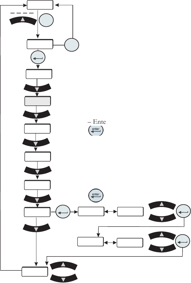
The analog output uses a 2-point calibration. Depending on how the analog
output is congured Type1, Type2 or Type 3, the HMI will display either volts,
millivolts or milliamps. The calibration procedure is:
– Start with default high and low endpoints each consisting of a voltage/current
value and a theoretical DAC value. This will permit calibration of either point
rst. Both ends must be calibrated for the entire calibration to be valid.
– Connect a 9.50v/0.40mv/20.00ma reference voltage/current meter to the DAC
output, pins 6 and 7.
– The HMI will display 9.50/0.40/20.00. Use the arrow keys to adjust the output
to match the display of 9.50v/0.40mv/20.00ma.
– Allow the DAC output and voltage reading to stabilize, approximately 10
seconds.
– Enter the measured reference voltage/current using the HMI by pressing the
key. The rmware will use this value and the theoretical DAC value and
those from the low end to calculate a linear gain and offset.
– The display will automatically go to the low calibration point.
– Use the arrow keys to adjust the output to match the displayed value. Allow the
DAC output and voltage to stabilize, approximately 10 seconds .
– Enter the measured reference voltage/current using the HMI by pressing the
key. The rmware will use this value and the theoretical DAC value and
Analog Output Calibration
those from the high end to calculate a
linear gain and offset.
– If the gain and offset are acceptable,
the calibration is accepted and the
calibration is now valid at the low end.
Otherwise, the calibration is rejected and
a bad calibration error message (Er 16)
is displayed.
Figure C-4 Analog Output Calibration Loop
Save calibration
Do not save calibration
Thermo Scientific
Appendix C
ThermoFlex C-7
Thermo Scientific
Table 3
Pin
1 White
2 NA
3 NA
4 White
5 NA
6 NA
7 Red
8 NA
9 Red (4th wire not connected to the control board)
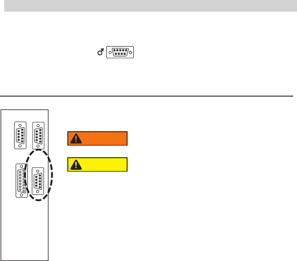
Figure C-5 Remote Sensor Connector
Remote Sensor Connector Pinout
1 2 3 4 5
6 7 8 9
1 2 3 4 5
6 7 8 9
1 2 3 4 5
6 7 8 9
1 2 3 4 5
6 7 8 9
8 7 6 5 4 3 2 1
15 14 13 12 11 10 9
RS232 RS485
A I/O REMOTE
SENSOR
Never apply line voltage to any of the connections.
WARNING
When operating a ThermoFlex7500-10000 with the remote
sensor enabled ensure the chiller's response to lowering the
setpoint does not result in operation below 10°C process
temperature. Operation below 10°C requires the use of
50/50 EG/water or 50/50 PG/water.
CAUTION