ThermoFlex-Manual.pdf - 第123页
Thermo Scientific Appendix C ThermoFlex C-7 Thermo Scientific T able 3 Pin 1 White 2 NA 3 NA 4 White 5 NA 6 NA 7 Red 8 NA 9 Red (4th wire not connected to the control board) Figure C-5 Remote Sensor Connector Remote Sensor…
Thermo Scientific
C-6 ThermoFlex
Appendix C
Thermo Scientific
Thermo Scientific
xx.x
xx.x
9.50
4.50
Ao Hi
Ao Lo
xx.x C
mode
rtd1
Flo
CAL
enter
enter
enter
enter
mode
r rtd
A in
Aout1
StorE
PrES1
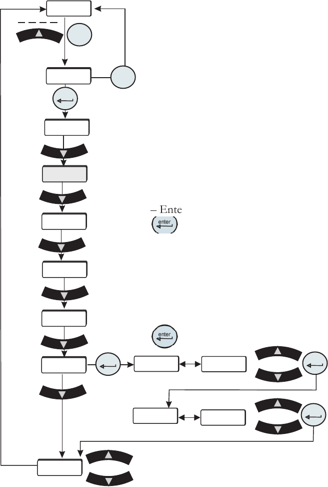
The analog output uses a 2-point calibration. Depending on how the analog
output is congured Type1, Type2 or Type 3, the HMI will display either volts,
millivolts or milliamps. The calibration procedure is:
– Start with default high and low endpoints each consisting of a voltage/current
value and a theoretical DAC value. This will permit calibration of either point
rst. Both ends must be calibrated for the entire calibration to be valid.
– Connect a 9.50v/0.40mv/20.00ma reference voltage/current meter to the DAC
output, pins 6 and 7.
– The HMI will display 9.50/0.40/20.00. Use the arrow keys to adjust the output
to match the display of 9.50v/0.40mv/20.00ma.
– Allow the DAC output and voltage reading to stabilize, approximately 10
seconds.
– Enter the measured reference voltage/current using the HMI by pressing the
key. The rmware will use this value and the theoretical DAC value and
those from the low end to calculate a linear gain and offset.
– The display will automatically go to the low calibration point.
– Use the arrow keys to adjust the output to match the displayed value. Allow the
DAC output and voltage to stabilize, approximately 10 seconds .
– Enter the measured reference voltage/current using the HMI by pressing the
key. The rmware will use this value and the theoretical DAC value and
Analog Output Calibration
those from the high end to calculate a
linear gain and offset.
– If the gain and offset are acceptable,
the calibration is accepted and the
calibration is now valid at the low end.
Otherwise, the calibration is rejected and
a bad calibration error message (Er 16)
is displayed.
Figure C-4 Analog Output Calibration Loop
Save calibration
Do not save calibration
Thermo Scientific
Appendix C
ThermoFlex C-7
Thermo Scientific
Table 3
Pin
1 White
2 NA
3 NA
4 White
5 NA
6 NA
7 Red
8 NA
9 Red (4th wire not connected to the control board)
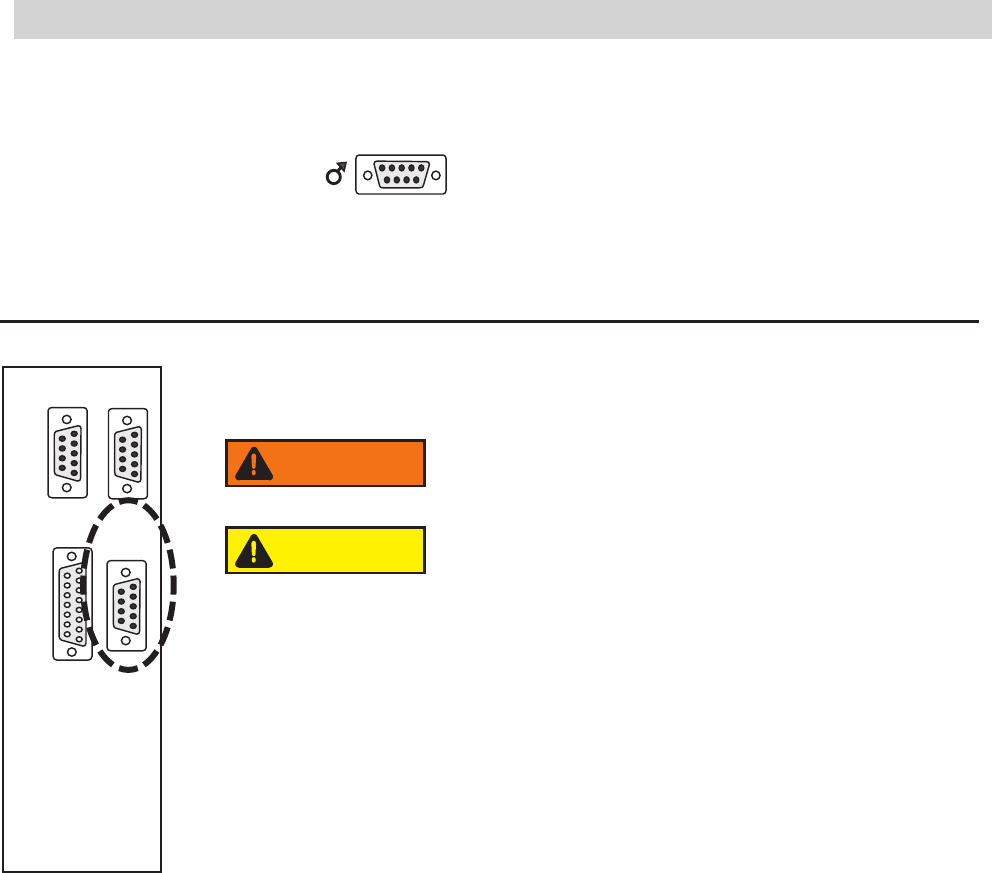
Figure C-5 Remote Sensor Connector
Remote Sensor Connector Pinout
1 2 3 4 5
6 7 8 9
1 2 3 4 5
6 7 8 9
1 2 3 4 5
6 7 8 9
1 2 3 4 5
6 7 8 9
8 7 6 5 4 3 2 1
15 14 13 12 11 10 9
RS232 RS485
A I/O REMOTE
SENSOR
Never apply line voltage to any of the connections.
WARNING
When operating a ThermoFlex7500-10000 with the remote
sensor enabled ensure the chiller's response to lowering the
setpoint does not result in operation below 10°C process
temperature. Operation below 10°C requires the use of
50/50 EG/water or 50/50 PG/water.
CAUTION
Thermo Scientific
C-8 ThermoFlex
Appendix C
Thermo Scientific
xx.x
xx.x
xx.x
xx.x
Rdt H
rtd H
rtd L
rdt L
xx.x C
mode
rtd1
Flo
CAL
enter
enter
enter
enter
enter
enter
mode
r rtd
A in
Aout1
StorE
PrES1
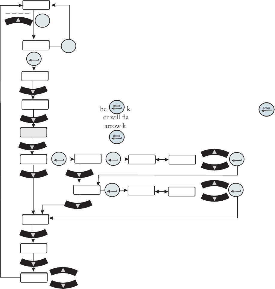
Remote Sensor Calibration
Figure C-6 Remote Sensor
Calibration Loop
This procedure requires a running chiller and a calibrated reference thermometer.
Note If it is more convenient, perform the low-end calibration before doing the
high-end.
Do not pick calibration points that are outside the safe operating limits of the uid
in your application. For example with water, 40°C and 5°C are typical high and low
calibration points.
Place the remote sensor and a calibrated reference thermometer in the high
temperature remote reservoir. Ensure the uid temperature is stabilized.
Press the
key and the controller will display rtd H. Press again and the
controller will ash between rtd H and the temperature.
Use the arrow keys to adjust the temperature to match the reference thermometer.
Press the
key again to accept the value.
Save calibration
Do not save calibration
Place the remote sensor and calibrated reference thermometer
in a low temperature reservoir. At the rtd L (low-end
calibration) display repeat the procedure.
After the low-end calibration is accepted StorE is displayed.
Press the up arrow to accept the calibration, press the down
arrow key to not accept it.
Note After pressing the up arrow button at the StorE
prompt wait several seconds before proceeding to ensure that
a bad calibration message (Er 16) does not appear. Premature
use of the keypad after pressing the up arrow may cancel the
bad calibration error message.