ThermoFlex-Manual.pdf - 第15页
ThermoFlex i Thermo Scientific Pr ef ace Compliance Third Party: CSA Listed - Laborator y equipment-electrical File # 105974_C_000 CLASS: 8721-05 CAN/CSA-C22.2 No . 61010-1-04 CLASS: 8721-85 ANSI/UL Standard 61010-1 Europ…
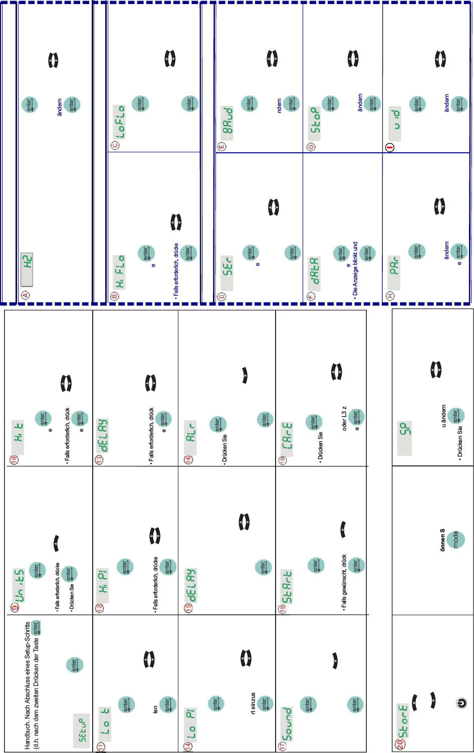
'UFNHQ6LH
'LH$Q]HLJHEOLQNWXQG]HLJWDEZHFKVHOQG Hi t und 42 an
)DOOVHUIRUGHUOLFKGUFNHQ6LH XPGHQ:HUWHLQ]XVWHOOHQ
'UFNHQ6LH XP]XUQlFKVWHQ$Q]HLJH]X
ZHFKVHOQ
'UFNHQ6LH
'LH$Q]HLJHEOLQNWXQG]HLJWDEZHFKVHOQG Lo t und 3 an
)DOOVHUIRUGHUOLFKGUFNHQ6LH XPGHQ
:HUWHLQ]XVWHOOHQ
'UFNHQ6LH
Über Lo t wird die Alarmschwelle
für niedrige Flüssigkeitstemperatur
eingestellt.
Bereich: +3°C bis +42°C
Werkseinstellung: 3°C
'UFNHQ6LH
'LH$Q]HLJHEOLQNWXQG]HLJWDEZHFKVHOQG Hi P1 und
GHQ6WDQGDUGZHUWDQ
)DOOVHUIRUGHUOLFKGUFNHQ6LH XPGHQ:HUWHLQ]XVWHOOHQ
'UFNHQ6LH
Über Hi P1 wird die Alarmschwelle für
die Entlastung der Pumpe bei hohem
Druck eingestellt.
Bereich: Je nach Pumpe verschieden
Werkseinstellung: Je nach Pumpe
verschieden
'LH$Q]HLJHEOLQNWXQG]HLJWDEZHFKVHOQGdELAY und 0 an
)DOOVHUIRUGHUOLFKGUFNHQ6LH XPGHQ:HUWHLQ]XVWHOOHQ
'UFNHQ6LH
dELAY gibt an, wie lange die Pumpe nach
Überschreiten der Hi P1 Alarmschwelle
noch weiterläuft, bevor sie abschaltet.
Bereich: Je nach Pumpe verschieden
Werkseinstellung: 0 Sekunden
'UFNHQ6LH
'LH$Q]HLJHEOLQNWXQG]HLJWDEZHFKVHOQG Lo P1
XQGGHQ6WDQGDUGZHUWDQ
)DOOVHUIRUGHUOLFKGUFNHQ6LH
XPGHQ
6WDQGDUGZHUWHLQ]XVWHOOHQ
'UFNHQ6LH
Über Lo P1 wird die Alarmschwelle
für die Entladung der Pumpe bei
niedrigem Druck eingestellt.
Bereich: Je nach Pumpe
verschieden
Werkseinstellung: Je nach
Pumpe verschieden
dELAY gibt an, wie lange die Pumpe
nach Überschreiten der Lo P1
Alarmschwelle noch weiterläuft,
bevor sie abschaltet.
Bereich: 0 bis 30 Sekunden
Werkseinstellung: 10 Sekunden
'LH$Q]HLJHEOLQNWXQG]HLJWDEZHFKVHOQGdELAY und 10 an
)DOOVHUIRUGHUOLFKGUFNHQ6LH XPGHQ:HUW
einzustellen
'UFNHQ6LH
'UFNHQ6LH
'LH$Q]HLJHEOLQNWXQG]HLJWDEZHFKVHOQGALr und fLt an
)DOOVJHZQVFKWGUFNHQ6LH
XPindC
anzuzeigen
'UFNHQ6LH
Schaltet den akustischen
Alarm des Geräts ein bzw. aus.
Bereich: on oder OFF
Werkseinstellung: on
'UFNHQ6LH
'LH$Q]HLJHEOLQNWXQG]HLJWDEZHFKVHOQGSound
und ON an
)DOOVJHZQVFKWGUFNHQ6LH
XPOFF
anzuzeigen
'UFNHQ6LH
'UFNHQ6LH
'LH$Q]HLJHEOLQNWXQG]HLJWDEZHFKVHOQGStArt und
OFF an
)DOOVJHZQVFKWGUFNHQ6LH XPON anzuzeigen
'UFNHQ6LH
Über StArt wird der automatische
Neustart ein- bzw. ausgeschaltet.
Bereich: on oder OFF
Werkseinstellung: OFF
'UFNHQ6LH
'LH$Q]HLJHEOLQNWXQG]HLJWDEZHFKVHOQGCArE und L1 an
)DOOVHUIRUGHUOLFKGUFNHQ6LH
XPGLH$Q]HLJH
DXI2))/RGHU/]XlQGHUQ
'UFNHQ6LH
Über CArE wird das Erinnerungsintervall für
die vorbeugende Reinigung der Luft- und
)OVVLJNHLWV¿OWHUGHV*HUlWVHLQJHVWHOOW
Bereich: off, L1 - 1000 Stunden,
L2 - 2000 Stunden, L3 -3000 Stunden
Werkseinstellung: L1
'UFNHQ6LH XPalle(LQVWHOOXQJHQ]XVSHLFKHUQ
Das Gerät startet automatisch.
'UFNHQ6LH XPallebQGHUXQJHQ]X
YHUZHUIHQXQG]XGHQ:HUNV6WDQGDUGHLQVWHOOXQJHQ
]XUFN]XNHKUHQ
'LH$Q]HLJHEOHLEWOHHU
'UFNHQ6LH
XPGHQ9RUJDQJQHX]XVWDUWHQ
Der Setup-Vorgang ist nun abgeschlossen.
Beim Start des Geräts wird die Temperatur
GHU3UR]HVVÀVVLJNHLWDQJH]HLJW
Falls gewünscht, können Sie den Sollwert
durch Drücken von
lQGHUQEHVWlWLJHQ
Über SP wird der Sollwert eingestellt.
Bereich: +5°C bis +40°C
Werkseinstellung: +20°C
'LH$Q]HLJHEOLQNWXQG]HLJWDEZHFKVHOQGSP und 20 an
)DOOVHUIRUGHUOLFKGUFNHQ6LH
XPGLH
(LQVWHOOXQJ]XlQGHUQ
'UFNHQ6LH
XPGHQQHXHQ6ROOZHUW]XVSHLFKHUQ
XQG]XU$Q]HLJHGHU7HPSHUDWXU]XUFN]XNHKUHQ
Falls zutreffend, stellen Sie die Optionen entsprechend den Feldern auf der rechten Seite ein. Für Geräte mit
analogen Ein- und Ausgängen (ACOM) siehe mitgelieferte zusätzliche Hinweise für den Schnellstart.
Schnellstart - Nur für die erste Inbetriebnahme — führen Sie die Schritte 9 bis 20 für alle Geräte aus.
**fLt = Fehler (Abschalten)
**indC = Anzeigen (Betrieb fortsetzen)
Über Hi t wird die Alarmschwelle für den
Übertemperaturalarm der Flüssigkeit eingestellt.
Bereich: +3°C bis +42°C
Werkseinstellung: +42°C
'UFNHQ6LH
'LH$Q]HLJHEOLQNWXQG]HLJWDEZHFKVHOQG UnitS und °C an
)DOOVHUIRUGHUOLFKGUFNHQ6LH XPGLH6NDODDXI)XP]XVFKDOWHQ
'UFNHQ6LH XP]XUQlFKVWHQ$Q]HLJH]XZHFKVHOQ
:LHGHUKROHQ6LHGHQ9RUJDQJIUGLH6NDOHQFlow
'XUFKÀXVVXQG3UHVVXUH'UXFN
'UFNHQ6LH
'LH$Q]HLJHEOLQNWXQG]HLJWDEZHFKVHOQGu id und 1 an
)DOOVHUIRUGHUOLFKGUFNHQ6LH XPGLH
(LQVWHOOXQJ]XlQGHUQ
'UFNHQ6LH
Über HiFLO wird die Alarmschwelle
IUKRKHQ'XUFKÀXVVHLQJHVWHOOW
Bereich: Je nach Pumpe
verschieden
Werkseinstellung: Je nach Pumpe
verschieden
'UFNHQ6LH
'LH$Q]HLJHEOLQNWXQG]HLJWDEZHFKVHOQGHiFLO und
GHQ6WDQGDUGZHUWDQ
)DOOVHUIRUGHUOLFKGUFNHQ6LH XPGHQ:HUWHLQ]XVWHOOHQ
'UFNHQ6LH
'UFNHQ6LH
'LH$Q]HLJHEOLQNWXQG]HLJWDEZHFKVHOQGLoFLO und
GHQ6WDQGDUGZHUWDQ
)DOOVHUIRUGHUOLFKGUFNHQ6LH
XPGHQ:HUW
einzustellen
'UFNHQ6LH
Über LoFLO wird die Alarmschwelle
IUQLHGULJHQ'XUFKÀXVVHLQJHVWHOOW
Bereich: Je nach Pumpe verschieden
Werkseinstellung: Je nach Pumpe
verschieden
'UFNHQ6LH
'LH$Q]HLJHEOLQNWXQG]HLJWDEZHFKVHOQGStoP und 1 an
)DOOVHUIRUGHUOLFKGUFNHQ6LH XPGLH
(LQVWHOOXQJ]XlQGHUQ
'UFNHQ6LH
Über StoP wird die Anzahl der Stopp-
Bits angegeben.
Bereich: 2 oder 1
Werkseinstellung: 1
u id (Geräte-ID) wird nur bei RS485
YHUZHQGHW=XU,GHQWL¿]LHUXQJYRQ
Geräten, die an den Port RS485
angeschlossen werden.
Bereich: 1 bis 99
Werkseinstellung: 1
'UFNHQ6LH
'LH$Q]HLJHEOLQNWXQG]HLJWDEZHFKVHOQGSEr und OFF an
)DOOVHUIRUGHUOLFKGUFNHQ6LH XPGHQ0RGXV
]XlQGHUQ
'UFNHQ6LH
Über SEr wird der Modus für die
serielle Kommunikation ein- und
DXVJHVFKDOWHWXQGNRQ¿JXULHUW
Bereich: off, rS232, rS485
Werkseinstellung: off
'UFNHQ6LH
'LH$Q]HLJHEOLQNWXQG]HLJWDEZHFKVHOQGBAud und 9600 an
)DOOVHUIRUGHUOLFKGUFNHQ6LH XPGLH
%DXGUDWH]XlQGHUQ
'UFNHQ6LH
Über BAud wird die Baudrate
(Geschwindigkeit) für die serielle
Kommunikation ausgewählt.
Bereich: 9600, 4800, 2400, 1200,
600 oder 300 Bit pro Sekunde.
Werkseinstellung: 9600
'UFNHQ6LH
'LH$Q]HLJHEOLQNWXQG]HLJWDEZHFKVHOQGdAtA und 8 an
'UFNHQ6LH
Über dAtA wird die Anzahl der
Bits angezeigt.
Anzeige: 8
'UFNHQ6LH
'LH$Q]HLJHEOLQNWXQG]HLJWDEZHFKVHOQGPAr und none an
)DOOVHUIRUGHUOLFKGUFNHQ6LH XPGLH
(LQVWHOOXQJ]XlQGHUQ
'UFNHQ6LH
PAr wird verwendet, um Fehler in der
'DWHQEHUWUDJXQJ]X¿QGHQ
Bereich: gleich, ungleich oder keine
Werkseinstellung: keine
2SWLRQ'XUFKÀXVV0HVVXPIRUPHU²6FKULWWH%XQG&
Wenn Ihr Gerät nicht über eine
serielle Kommunikation verfügt,
siehe Schritt 20.
Siehe Schritt 20
Option - Serielle Kommunikation (DCOM) — Schritte D bis I
UnitS sind die Einheiten für Temperatur,
)OVVLJNHLWVGXUFKÀXVVRSWLRQDO und Druck.
Einheiten: °C/°F GPM/LPM
PSI/Bar/KPAS
Werkseinstellungen: °C, Gallonen, PSI
'UFNHQ6LH
'LH$Q]HLJHEOLQNWXQG]HLJWDEZHFKVHOQGHZ und 60 an
)DOOVHUIRUGHUOLFKGUFNHQ6LH XPGLH
)UHTXHQ]]XlQGHUQ
'UFNHQ6LH
Wenn Ihr Gerät nicht über einen
'XUFKÀXVV0HVVXPIRUPHURGHUVH-
rielle Kommunikation verfügt, siehe
Schritt 20.
Option - Variabler Spannungsbereich — Schritt A
Über HZ wird bei Geräten mit variablem
Spannungsbereich die Frequenz des Stromnetzes
angegeben. Über die gewählte Frequenz wird die
festgelegte Überdruck-Standardeinstellung der
Firmware automatisch justiert.
Bereich: 50 oder 60 Hz Standard: 60 Hz
I
'UFNHQ6LH XPGHQ
6HWXS9RUJDQJIRUW]XVHW]HQ
HINWEIS:(LQLJH%HUHLFKH6WDQGDUGZHUWHVLQG
DEKlQJLJYRQGHU3XPSHVLHKH$EVFKQLWWLP
+DQGEXFK1DFK$EVFKOXVVHLQHV6HWXS6FKULWWV
GKQDFKGHP]ZHLWHQ'UFNHQGHU7DVWH
N|QQHQ6LHGHQ6FKULWWQLFKWZLHGHUKROHQXP
.RUUHNWXUHQYRU]XQHKPHQbQGHUXQJHQkönnen
6LHQDFKGHP(LQVFKDOWHQGHV*HUlWVYRUQHKPHQ
HINWEIS Diese Funktion ist nur aktiv, wenn
GDV*HUlWDXI$EVFKDOWHQNRQ¿JXULHUWLVW
siehe Schritt 16
.
HINWEIS Diese Funktion ist nur
aktiv, wenn das Gerät auf Abschalten
NRQ¿JXULHUWLVWVLHKH6FKULWW
.
$/UNRQ¿JXULHUWGLH5HDNWLRQGHV*HUlWVDXI
7HPSHUDWXU'UXFNXQGRSWLRQDO'XUFKÀXVV
Alarmzustände - entweder Abschaltung
(fLt) oder Betrieb fortsetzen (indC). Weitere
Informationen siehe Abschnitt 4 im Handbuch.
Bereich: fLt* oder indC**
Werkseinstellung: fLt

ThermoFlex i
Thermo Scientific
Preface
Compliance Third Party:
CSA Listed - Laboratory equipment-electrical
File # 105974_C_000
CLASS: 8721-05 CAN/CSA-C22.2 No. 61010-1-04
CLASS: 8721-85 ANSI/UL Standard 61010-1
European Union ( EU ) LVD & EMC
Our evaluation has demonstrated compliance with the following EU
directives, as indicated by the CE Mark located on the chiller's nameplate
and the Declaration of Conformity in the back of this manual.
2004/108/EC - Electromagnetic Compatibility Directive (EMC):
EN61326-1:2006 - Electrical equipment for measurement, control, and
laboratory use - EMC requirements
2006/95/EC - Low Voltage Directive (LVD):
EN61010-1:2001 - Safety requirements for electrical equipment for
measurement, control, and laboratory use - general requirements
WEEE This product is required to comply with the European Union’s Waste
Electrical & Electronic Equipment (WEEE) Directive 2002/96/EC. It is
marked with the following symbol:
Thermo Fisher Scientic has contracted with one or more recycling/
disposal companies in each EU Member State, dispose of or recycle this
product through them. Further information on Thermo Fisher Scientic’s
compliance with these Directives is available at:
www.thermoscientic.com/WEEERoHS

ii ThermoFlex
Preface
Thermo Scientific
After-sale Support Thermo Fisher Scientic is committed to customer service both during
and after the sale. If you have questions concerning the chiller operation,
or questions concerning spare parts or Service Contracts, call our Sales,
Service and Customer Support phone number, see this manual's inside
cover for contact information.
When calling, please refer to the labels on the inside cover. These labels list
all the necessary information needed to properly identify your chiller.
Feedback We appreciate any feedback you can give us on this manual. Please e-mail
us at tcmanuals@thermosher.com. Be sure to include the manual part
number and the revision date listed on the front cover.
Warranty Thermo Scientic ThermoFlex chillers have a warranty against defective
parts and workmanship for 24 months (excluding MD 1/MD 2 Magnetic
Drive and P 1/P 2 Positive Displacement pumps which are warranted
for 12 months) from date of shipment. See back page for more details.
Unpacking If the chiller has a line cord it is located under the shipping crate’s lid. Do
not discard the lid until the cord is located.
Retain all cartons and packing material until the chiller is operated and
found to be in good condition. If it shows external or internal damage
contact the transportation company and le a damage claim. Under ICC
regulations, this is your responsibility.
Out of Box Failure
An Out of Box Failure is dened as any product that fails to operate in
conformance with sellers published specications at initial power up. Install
the chiller in accordance with manufacturer's recommended operating
conditions within 30 days of shipment from the seller.
Any Temperature Control product meeting the denition of an Out of
Box Failure must be packed and shipped back in the original packaging
to Thermo Fisher Scientic for replacement with a new chiller; seller
to pay the cost of shipping. Customer must receive a Return Material
Authorization (RMA) from Thermo Fisher prior to shipping.