ThermoFlex-Manual.pdf - 第56页
Section 3 3-18 ThermoFlex Thermo Scientific Initial Filling Ensure the reser voir drain plug on the back of the chiller is in place, or the Before usi…
Section 3
ThermoFlex 3-17
Thermo Scientific
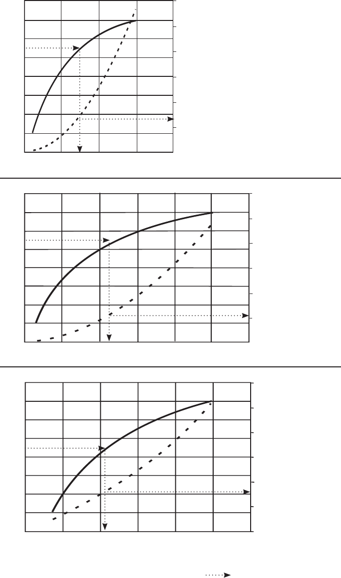
ThermoFlex24000
Example:
Follow the lines.
Start with a known, e.g., facility water temperature.
A - go across to temperature curve
B - go down or up to determine the minimum
required facility ow.
C - Where B crosses the PSID curve, go across to
determine the minimum required PSID.
Facility Temperature °C
40
35
30
25
20
15
10
5
5 10 15 20 25 30
Facility Flow - GPM
Facility Pressure Drop PSID
Facility Pressure Drop PSID
30
25
20
15
10
5
PSID
A
B
C
°C
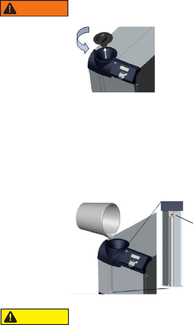
ThermoFlex15000/20000
Example: See below.
5 10 15 20
Facility Flow - GPM
°C
PSID
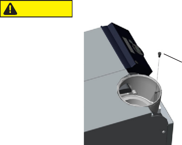
ThermoFlex7500/10000
Example: See below.
A
B
C
Facility Temperature °C Facility Temperature °C
40
35
30
25
20
15
10
5
40
35
30
25
20
15
10
5
5 10 15 20 25 30
Facility Flow - GPM
Facility Pressure Drop PSID
30
25
20
15
10
5
30
25
20
15
10
5
PSID
A
B
C
°C
Section 3
3-18 ThermoFlex
Thermo Scientific
Initial Filling
Ensure the reservoir drain plug on the back of the chiller is in place, or the
Before using any uid refer to the manufacturer’s MSDS for handling
precautions.
Slowly
comply may result in internal spillage.
Note
O FLO) causing the chiller to shut down.
Since the reservoir capacity may be small compared to your application and
keep the system topped off when external circulation is started.
Figure 3-6 Reservoir Cap
Before replacing the reservoir cap ensure the reservoir sight tube ball
stopper is securely in place, see next page.
Replace the reservoir cap by screwing it clockwise. Cap should be hand tight.
Reservoir Sight Tube & Ball
MAX
LEVEL
MIN
LEVEL
Figure 3-7 Reservoir Sight Tube & Ball
WARNING
Locate and remove the reservoir cap by
unscrewing it counterclockwise.
To prevent the introduction of particulates
Section 6.
CAUTION
Section 3
ThermoFlex 3-19
Thermo Scientific
Fluid Top Off
Remove the reservoir cap by unscrewing it counterclockwise.
Slowly
failure to comply may result in internal spillage.
Note
O FLO
expand when heated.
Note
already in the reservoir will temporarily affect the chiller's stability
performance.
Before replacing the reservoir cap ensure the reservoir sight tube
ball stopper is securely in place.
Reservoir Ball Stopper
Figure 3-8 Reservoir Ball Stopper
CAUTION