ThermoFlex-Manual.pdf - 第6页
ThermoFlex Contents Thermo Scientific Section 5 Additional Options/Accessories ................................................ 5-1 AutoR ell .......................................................................…
ThermoFlex
Thermo Scientific
Contents
Quick Start
Preface .................................................................................................................................i
Compliance ..............................................................................................................i
WEEE .....................................................................................................................i
After-Sale Support .................................................................................................ii
Unpacking ...............................................................................................................ii
Warranty ..................................................................................................................ii
Feedback ..................................................................................................................ii
Section 1 Safety ..................................................................................1-1
Warnings ..............................................................................................................1-1
Section 2 General Information .............................................................2-1
Description .........................................................................................................2-1
Specications ......................................................................................................2-1
Section 3 Installation ...........................................................................3-1
Site Requirements ..............................................................................................3-1
Electrical Requirements ....................................................................................3-2
Hard Wire Installation .......................................................................................3-8
Plumbing Requirements ....................................................................................3-9
Process Fluid Requirements ...........................................................................3-11
Compatibility with Approved Fluids ............................................................3-12
Additional Fluid Information ........................................................................3-14
Process Water Quality and Standards ...........................................................3-14
Facility Water Quality - Standards and
Recommendations (water-cooled chillers) ...................................................3-15
Facility Water Requirements (water-cooled chillers) ...................................3-17
Initial Filling .....................................................................................................3-18
Fluid Top Off ...................................................................................................3-19
Section 4 Operation .........................................................................................................4-1
Basic Controller ..................................................................................................4-1
Setup ....................................................................................................................4-2
Start Up ...............................................................................................................4-2
Controller Loops ................................................................................................4-4
Setpoint Loop .....................................................................................................4-5
Setup Loop ..........................................................................................................4-6
Shut Down ........................................................................................................4-12
ThermoFlex
Contents
Thermo Scientific
Section 5 Additional Options/Accessories ................................................5-1
AutoRell .........................................................................................................5-1
InternalDICartridge ........................................................................................5-2
P1P2T1PumpPressureRelief Valve(InternalConguration) .............. 5-3
P1P2T1PumpPressureRelief Valve(ExternalConguration) ............5-4
FlowControlwithFlowReadout ....................................................................5-5
P1P2T1PumpPressureRelief withFlowReadout ................................. 5-5
T5PumpFlowControl ....................................................................................5-6
AntiDrainback ...................................................................................................5-6
SEMI ....................................................................................................................5-6
OtherAccessories ............................................................................................5-10
Section 6 Preventive Maintenance............................................................................... 6-1
PreventiveMaintenanceTimer .......................................................................6-1
FluidBagFilter ...................................................................................................6-2
FluidDiffuser .....................................................................................................6-2
ReservoirCleaning .............................................................................................6-3
FluidMaintenance .............................................................................................6-3
CondenserFilter .................................................................................................6-4
ChillerSurface ....................................................................................................6-5
Hoses ...................................................................................................................6-5
DIFilter(Optional) ..........................................................................................6-6
TestingtheSafetyFeatures ...............................................................................6-7
DiagnosticLoop ...............................................................................................6-7
Section 7 Troubleshooting .....................................................................7-1
OperationalErrorCodes ..................................................................................7-1
Checklist ............................................................................................................7-10
Verifying/AdjustingtheControllerPIDValues .........................................7-13
Section 8 Additional Information ............................................................8-1
Draining ...............................................................................................................8-1
WettedMaterials .................................................................................................8-3
InternalProcessFluidTemperatureSensor(rdt1)Calibration ...................8-4
ProcessFluidPressure(P1)TransducerCalibration ...................................8-6
OptionalProcessFluidFlow(FLo)TransducerCalibration ......................8-8
ClearingSEr1Message ....................................................................................8-10
Decommissioning/Disposal ..........................................................................8-11
Shipment/Storage ............................................................................................8-11
Appendix A CountrySpecic230VAC,50Hz,1ØRequirements
Appendix B VoltageCongurationInstructions
Appendix C AnalogI/0andRemoteSensor
Appendix D SerialCommunications
Declaration of Conformity
WARRANTY
MIN
LEVEL
MAX
LEVEL
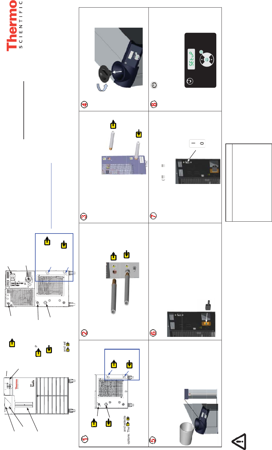
Slowly fill reservoir with clean process fluid (see Table 1),
utilizing sight tube for easy fluid level monitoring. When the reser-
voir is full replace the reservoir cap, hand tight. Since the reservoir
capacity may be small compared to your application and air may
need to be purged from the lines, have extra cooling fluid on hand
to keep the system topped off when external circulation is started.
Press .
The controller will display SEtuP.
Note: If the unit is equipped with a deionization filter cartridge
refer to the manual, Section 5, for installation.
Please see reverse side for additional steps.
Pull out the plastic shipping plugs.
Remove the reservoir cap by unscrewing it counter-
clockwise.
Verify the appropriate voltage. For units supplied with a line cord,
insert female end of power cord into chiller and then insert male end
of power cord into power outlet. (The line cord is located under the
shipping crate’s lid. Do not discard the lid
until the cord is located.)
Connect the ThermoFlex FACILITY OUTLET (A) to your facility
water return or drain. Connect the ThermoFlex FACILITY INLET (B)
to your facility water supply. Ensure the connections are sealed and
secure.
What you need to get started:
• An adjustable wrench
• Facility water supply and return (water-cooled units)
• Appropriate hose or plumbing
• Appropriate size clamps or connection type
• Teflon
®
Tape or appropriate sealant
Safety Precautions:
The unit is designed for indoor use only.
Never place unit in a location where excessive heat, moisture, inadequate
ventilation, or corrosive materials are present.
Never connect process fluid lines to your facility water supply or to any
pressurized liquid source.
If your unit is equipped with a positive displacement pump (P1 or P2),
ensure your application plumbing lines and fittings are rated to withstand a
minimum of 185 psi.
Before using any fluid or performing maintenance where contact with the
fluid is likely refer to the manufacturer’s MSDS for handling precautions.
For water-cooled units only.
See Figure A.
See Figure B.
See Figure B. See Figure B.
See Figure B.
See Figure B.
See Figure A.
See Figure A.
Connect the ThermoFlex PROCESS OUTLET (A) to the fluid inlet
on your application. Connect the ThermoFlex PROCESS INLET (B) to
the fluid outlet on your application. Ensure the connections are sealed
and secure. For air-cooled units skip to Step 4.
For ThermoFlex900 through 10000 units, place the circuit
protector to the on ( I ) position. The controller display will indicate
a series of scrolling bars (
). The bars will scroll upward
indicating the unit is initializing, this takes approximately 15 sec-
onds. For other units the bars appear when power is supplied to
the unit.
B
A
B
A
PROCESS
INLET
PROCESS
OUTLET
FACILITY
INLET
FACILITY
OUTLET
Note: Be careful not
to fill the reservoir
above MAX LEVEL fill
line. This will result in
a unit over flow error
(O FLO) which will
cause the unit to shut
down.
Thermo Scientific Part Number U00945
Rev. 11/19/2012
Note: ThermoFlex900-5000 units equipped
with the V
ariable Voltage or Global Voltage
option have a voltage configuration panel
located behind an access panel on the rear
of the unit. Refer to the V
oltage Instruction
Sheet shipped with the unit, or see manual
Appendix B.
Note: For units requiring hard wiring see
Section 3 in the manual.
Water-cooled units only
FACILITY
INLET
FACILITY
OUTLET
PROCESS
INLET
PROCESS
OUTLET
Use of any fluid not listed below will void the
manufacturer’s warranty.
Filtered/Single Distilled Water
Deionized water (1-3 MΩ-cm, compensated)
0 – 75% Ethylene Glycol/Water
0 – 75% Propylene Glycol/Water
Table 1 - Acceptable Fluids:
Facility Water Connections (FNPT)
ThermoFlex1400 - 5000 Inlet/Outlet ½” cast bronze
ThermoFlex7500 - 10000 Inlet/Outlet ¾” cast bronze
ThermoFlex15000 - 24000 Inlet ¾” cast bronze
ThermoFlex15000 - 24000 Outlet ¾” stainless steel
Controller
See Step 8.
Power Button
See Step 8.
Integrated Funnel
See Step 5.
Level Indicator
See Step 5.
Figure A
Reservoir Cap
See Step 4.
Process Outlet -
See Steps 1 and 2.
Process Outlet -
(ThermoFlex900-
5000 units with PD
pumps and flow
transducers)
Circuit Protector
See Step 7.
Power Inlet for units
not hard-wired
See Step 6.
Process Inlet -
See Steps 1 and 2.
Facility Inlet
See Steps 1 and 3.
Facility Outlet
See Steps 1 and 3.
Water-cooled units only
Figure B
Figure B is typical.
Locations vary with unit size
and selected options. The
labels identify the
exact location.
Locations vary with
unit size and selected
options. The
labels identify the exact
location.
Process Fluid Connections (FNPT)
Outlet
ThermoFlex900 - 10000 P 1 P 2 T0 T 1 1/2" cast bronze
ThermoFlex3500 - 5000 P 3 P 4 3/4" cast bronze
ThermoFlex7500 - 24000 P 3 P 5 T 5 1" wrought copper
Inlet - Same size as outlet all units stainless steel
Supplied Adapters
P 1 P 2 T0 T 1 1/2" x 3/8'' Polyethylene and 1/2" x 1/2" Nylon
P 3 P 4 3/4 MPT x 1/2 barb PVC
P 3 P 5 T 5 1" MPT x 1" Barb PVC and 1" MPT x 3/4" Barb PVC