ThermoFlex-Manual.pdf - 第65页
Section 4 ThermoFlex 4-7 Thermo Scientific diA9 SP SEtuP enter mode mode mode mode xx.x C xx.x C xx xx Hi t UnitS Lo t Lo t xx xx xx xx Hi P1 Lo P1 Hi P1 dELA Y enter enter enter enter enter enter enter enter enter Hi t U…
Section 4
4-6 ThermoFlex
Thermo Scientific
Setup Loop
( )
Use the Setup Loop to adjust/verify the following controller settings.
• Scales: temperature in °C or °F, ow in liters per minute or gallons per
minute (only chillers with an optional ow transducer), and pressure in
PSI, bar or kPa
• High and low temperature alarm limits
• High and low pump discharge pressure alarm limits and time delays
• Chiller reaction to a temperature, pressure or ow (optional) alarm limit
(continue to run or shut down)
• Audible alarm enabled/disabled
• View/change the fan speed (ThermoFlex2500 air-cooled only)
• Auto restart feature enabled/disabled
• Preventive care cleaning frequency reminder for air and uid lters
Optional Features:
• Global voltage
• Analog I/O
• Auto rell alarm
• DI lter cartridge preventive maintenance interval
• High/low ow alarm limits
• Serial communications
• Anti drainback valve position
• Save or not save
all
changes
To enter the Setup Loop ensure the controller display is either a blank
screen (chiller off) or displaying the process uid temperature. Press the
key and the display will indicate SP, press it again to display SEtuP.
Press the
key to continue, or press twice to return to the
process uid temperature or blank display.
Use
to sequence down through the loop. Use to
sequence back through the loop up to the Hi t display, see next page.
To change any parameter:
Press the
key.
Use the keys to change a displayed value.
Press
key to conrm the change and bring up the next display.
Section 4
ThermoFlex 4-7
Thermo Scientific
diA9
SP
SEtuP
enter
mode
mode
mode
mode
xx.x C
xx.x C
xx
xx
Hi t
UnitS
Lo t
Lo t
xx
xx
xx
xx
Hi P1
Lo P1
Hi P1
dELAY
enter
enter
enter
enter
enter
enter
enter
enter
enter
Hi t
UnitS
degx
Lo P1
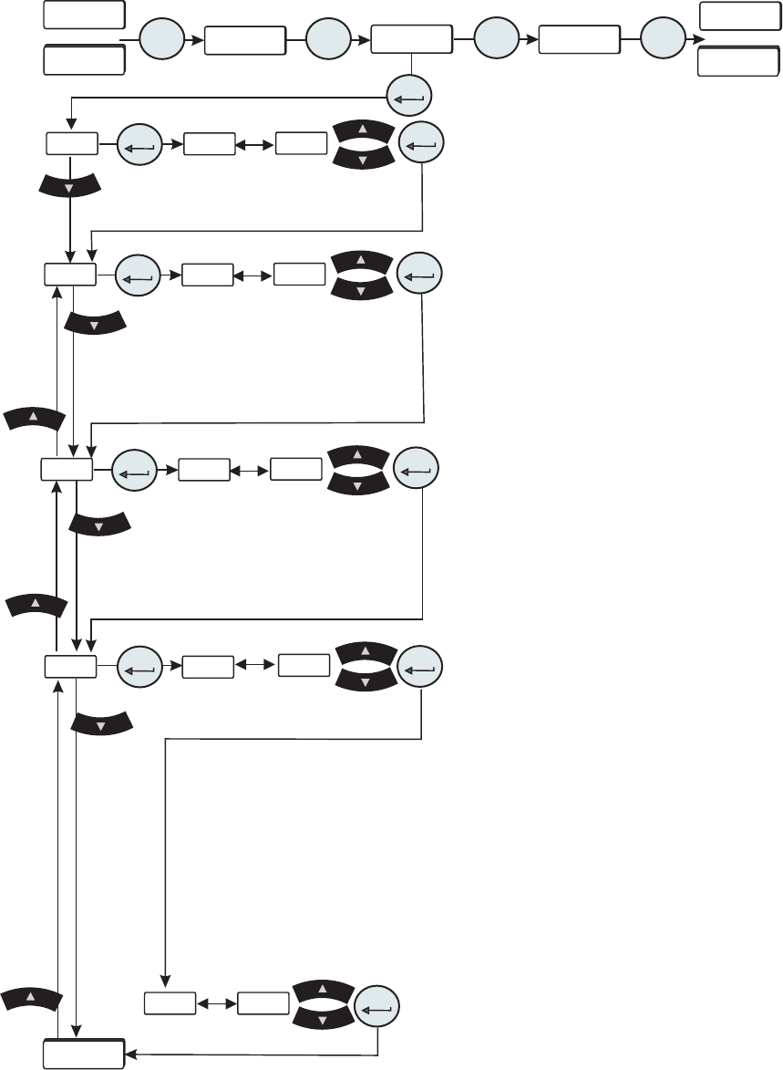
Figure 4-6 Setup Loop (All Chillers)
or
or
Continued on next page.
• UnitS are the temperature, uid ow (only chillers with an
optional ow transducer) and pressure display scales.
Scales:
°C or °F Defaults: °C
GPM or LPM GPM
PSI, Bar or kPa PSI
• Hi t is the uid's High Temperature alarm limit.
Range:
+3°C to +42°C Default: +42°C
Exceeding this limit ashes Hi t and, if enabled, sounds the
alarm. The chiller reaction depends on the alarm conguration
(see ALr on next page).
• Lo t is the uid's Low Temperature alarm limit.
Range: +3°C to +42°C
Default: +3°C
Falling below this limit ashes Lo t and, if enabled, sounds
the alarm. The chiller reaction depends on the alarm
conguration (see ALr on next page).
• Hi P1 is the pump's High Pressure discharge alarm limit.
T 1 T 0 Pump Range: 3 to 100 PSI Default: 100 PSI
T 5 Pump Range: 2 to 105 PSI Default: 105 PSI
P 1 P 2 Pump Range: 3 to 100 PSI Default: 100 PSI
P 3 Pump 60Hz Range: 3 to 46 PSI Default: 46 PSI
P 3 Pump 50Hz Range: 3 to 32 PSI Default: 32 PSI
P 4 Pump 60Hz Range: 3 to 85 PSI Default: 85 PSI
P 4 Pump 50Hz Range: 3 to 60 PSI Default: 60 PSI
P 5 Pump 60Hz Range: 3 to 87 PSI Default: 87 PSI
P 5 Pump 50Hz Range: 3 to 56 PSI Default: 56 PSI
Exceeding this limit ashes Hi P1 and, if enabled, sounds
the alarm (see Sound on next page).
• dELAY is the length of time the pump can exceed the
Hi P1 alarm limit. Note This feature is only active if the
chiller is congured to shut down with a pressure alarm.
P
1, P 2, T 0 and T 1 Range: 0 to 30 seconds
Default: 0 seconds
P 3 - P 5, T 5 Range: 0 to 60 seconds Default: 0 seconds
Exceeding this limit ashes Hi P1 and, if enabled, sounds
the alarm. The chiller reaction depends on the alarm
conguration (see ALr on next page).
Section 4
4-8 ThermoFlex
Thermo Scientific
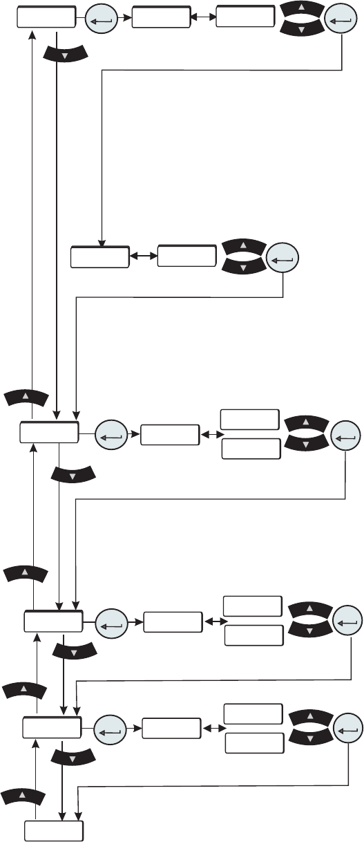
Figure 4-6 Setup Loop (All Chillers)
• Lo P1 is the pump's Low Pressure discharge alarm
limit.
T 0 T 1 Pump Range: 3 to 100 PSI Default: 4 PSI
T 5 Pump Range: 4 to 105 PSI Default: 4 PSI
P 1 P 2 Pump Range: 3 to 100 PSI Default: 4 PSI
P 3 Pump 60Hz Range: 3 to 46 PSI Default: 4 PSI
P 3 Pump 50Hz Range: 3 to 32 PSI Default: 4 PSI
P 4 Pump 60Hz Range: 3 to 85 PSI Default: 4 PSI
P 4 Pump 50Hz Range: 3 to 60 PSI Default: 4 PSI
P 5 Pump 60Hz Range: 3 to 87 PSI Default: 4 PSI
P 5 Pump 50Hz Range: 3 to 56 PSI Default: 4 PSI
Going below this limit ashes Lo P1 and, if enabled,
sounds the alarm.
• dELAY is the length of time the pump can exceed
the Lo P1 alarm limit. Note This feature is only active
if the chiller is congured to shut down with a pressure
alarm.
Range: 0 to 30 seconds
Default: 10 seconds
Exceeding this limit ashes Lo P1 and, if enabled,
sounds the alarm. The chiller reaction depends on the
ALr alarm conguration set below.
• ALr is used to congure the chiller's reaction for
exceeding an alarm limit (temperature, pressure and
optional ow). The chiller will either shut down (FLt)
or continue to run (indC). In each conguration, the
controller will display the error code and sound the
audible alarm, if enabled.
Range:
FLt or indC Default: FLt
• FAnSP is used to control the fan speed (air-cooled
2500 only). Auto allows the fan to run under the
conditions listed in Section 3. Selecting Hi allows
the fan to run at high speed all the time. Note Hi is
required for chillers to achieve a ThermoFlex2500 watt
cooling capacity.
Range:
Auto or Hi Default: Auto
• Sound is used to enable/disable the audible alarm.
Range:
on or oFF Default: on
Continued on next page.
Continued from previous page
enter
enter
enter
Sound
FAnSP
ALr
Lo P1
Lo P1
xx
xx
on
Auto
oFF
Hi
Sound
FAnSP
enter
enter
StArt
ALr
enter
FLt
indC
enter
enter
enter
dELAY