ThermoFlex-Manual.pdf - 第72页
Section 5 5-2 ThermoFlex Thermo Scientific A par tial ow DI lter cartridge is designed to maintain water resistivity between 1 and 3 M Ω- cm. Note T he DI option results in a 0.5 g pm reduction of available o w . Do …
ThermoFlex 5-1
Thermo Scientific
Auto Refill
The auto rell uid must also meet water quality standards or the valve may
fail to operate as designed, see Section 3.
The auto rell valve input pressure must be < 80 PSI to ensure the valve
functions properly.
The auto rell operates when all of the following conditions are met:
• Fluid is available
• The chiller is turned on
• The uid reaches a low level condition.
The auto rell shuts off when:
• The uid reaches the correct operating level.
• The delay timer exceeds user ll time entered in the Setup Loop, see
Section 4. If FLt is selected in the Setup Loop the chiller also shuts
down. (If indC is selected the chiller continues to run.) In either case
the controller will display rEFIL.
• The chiller shuts down for any reason.
Setting the ll time to 0 disables auto rell. If a low level condition occurs
the chiller will:
• If Indc is selected, continue to run and the controller displays Add.
• If FLt is selected, shut down and the controller displays LLF.
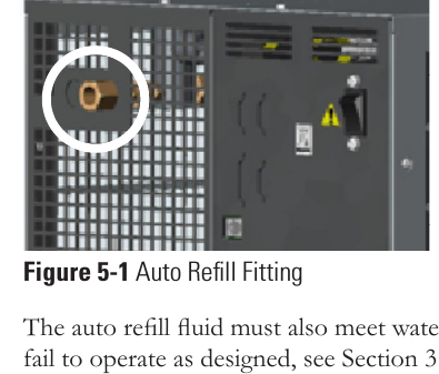
Figure 5-1 Auto Refill Fitting
Section 5 Options/Accessories
The Auto Rell provides makeup uid to replace any uid lost to evaporation,
etc. It requires a pressurized uid source connection to the ¼" Female Pipe
Thread tting on the rear of the chiller. (If Teon
®
tape is used, ensure the
tape does not cover the connection's starting-end thread.)
Note ThermoFlex7500 through 24000s with a P3 or P5 or ThermoFlex7500s
and 10000s with a T5 pump have a ¼" Male brass plug installed in the
connection, remove the plug before connecting the makeup uid.
Section 5
5-2 ThermoFlex
Thermo Scientific
A partial ow DI lter cartridge is designed to maintain water resistivity
between 1 and 3 MΩ-cm.
Note
The DI option results in a 0.5 gpm reduction of available ow.
Do not use a Deionization (DI) lter cartridge with Inhibited EG or
Inhibited PG. A DI lter will remove inhibitors from the solution ren-
dering the uid ineffective against corrosion protection. Also, inhibi-
tors increase uid conductivity.
The Puralite sensor on the back of the chiller turns red when the cartridge
needs changing (< 1 MΩ-cm), see Section 6. Note The Puralite sensor that
comes with the DI cartridge requires a separate power source.
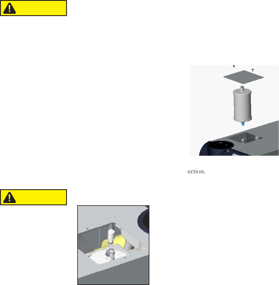
Remove the two thumbscrews securing
the DI access panel. Remove the
new cartridge from the shipping bag.
The cartridge has a blue and a white
connector. Lower the cartridge into the
chiller with the blue connector facing
downward. Press down on the cartridge
lightly to engage and then rotate it ¼ turn
clockwise (do not over rotate) or until you
feel the lter click into place.
If there is a cartridge in place, rst undo
the hose tting by pressing on the quick
disconnect located on the top white connection.
The DI Cartridge will overpressurize if it is removed from the chiller
before removing the hose tting.
Next rotate the cartridge ¼ turn counter-
clockwise and then pull the cartridge straight
up to remove it.
Push the hose tting into the quick disconnect
located on the white end of the cartridge.
Replace the access panel and thumbscrews.
Note The cartridge can be changed with the
chiller running, however, since the cartridge
runs in a parallel arrangement, disconnecting the cartridge adds 0.5 gpm to
the main ow. The additional ow will cause an increase in system pressure
which may cause a high uid pressure fault.
Internal DI
Cartridge
Quick Disconnect
Hose Fitting
Figure 5-3 DI Fittings
Figure 5-2 Internal DI Cartridge
Blue Connector
White Connector
Access Panel
CAUTION
CAUTION
Section 5
ThermoFlex 5-3
Thermo Scientific
P 1 P 2 T 0 T 1 Pump
Pressure Relief Valve
(Internal Configuration)
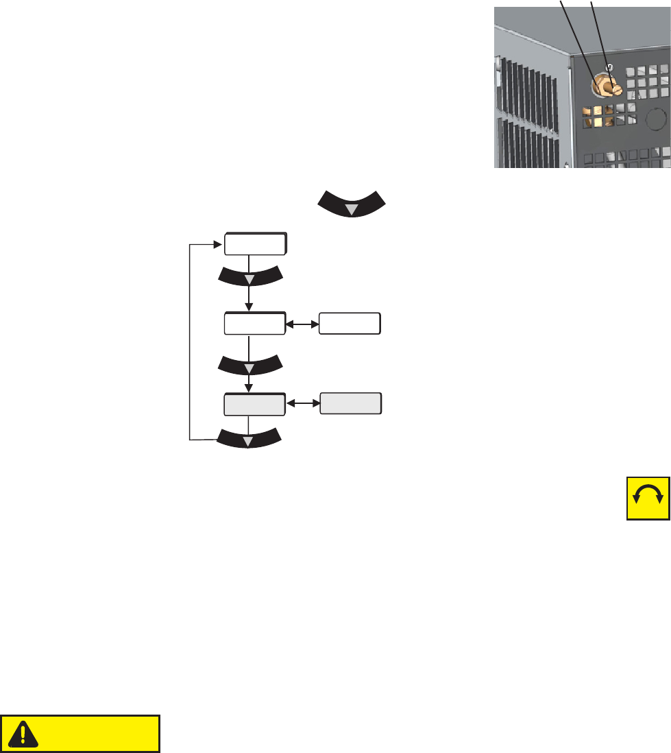
Figure 5-5 Main Loop
Use the pressure relief valve, located on the top
left rear of the chiller, to set the desired system
back pressure to your application. The valve is
factory preset to 80 ± 5 psi (5.5 ± 0.4 bar).
If the chiller is not plumbed to an application, set
the pressure by installing a loop of hose
equipped with a shut-off valve between the
supply and return ttings. Start the chiller and
allow it to prime, then close the valve.
Use the controller's to display P 1, it should display 80 ± 5 psi.
Adjusting Screw
Packing Nut
Use a screwdriver to turn the adjusting screw (counterclockwise to
reduce pressure) until the controller displays the desired setting.
Note Due to internal back pressure, the minimum pressure setting for a
deadheaded P 2 pump is 32 psi (2.2 bar), and 8 psi (0.6 bar) for a P 1 (these
settings prohibit external ow from the chiller).
If the chiller is plumbed to an application, ensure the chiller is off. Then back out
the adjusting screw counterclockwise to reduce pressure. Turn the chiller
on. Ensure that there is back pressure in the system. Turn the adjusting
screw until the controller displays the desired setting.
Do not exceed 100 psi (6.9 bar).
When complete, inspect the area around the
5
/
8
" packing nut for uid leaks.
If uid is present, slightly tighten the nut and reinspect.
Note Should the chiller start to vibrate the valve setting may be the cause.
Changing the pressure setting ± 5 psi (0.3 bar) will eliminate the vibration.
Figure 5-4 Nut and Screw
P1
FLo
xx.x C
80
xx
-+
PSI/KPa
CAUTION