ThermoFlex-Manual.pdf - 第74页
Section 5 5-4 ThermoFlex Thermo Scientific Figure 5-7 Main Loop P 1 P 2 T 0 T 1 Pump Pressure Relief V alve (External Configuration) Use the pressure relief valv e to set the desired system back pressure (P1) to y our appl…
Section 5
ThermoFlex 5-3
Thermo Scientific
P 1 P 2 T 0 T 1 Pump
Pressure Relief Valve
(Internal Configuration)
Figure 5-5 Main Loop
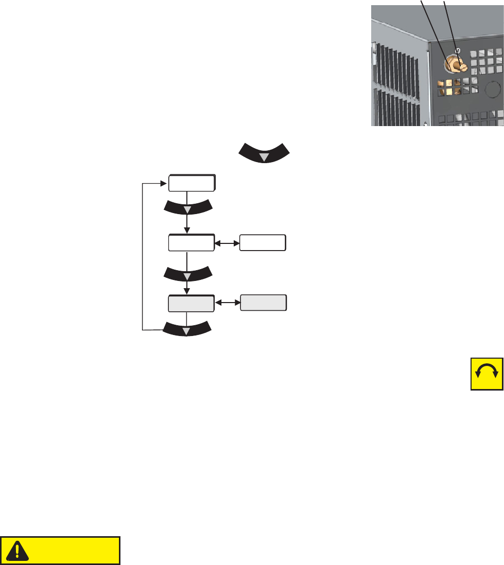
Use the pressure relief valve, located on the top
left rear of the chiller, to set the desired system
back pressure to your application. The valve is
factory preset to 80 ± 5 psi (5.5 ± 0.4 bar).
If the chiller is not plumbed to an application, set
the pressure by installing a loop of hose
equipped with a shut-off valve between the
supply and return ttings. Start the chiller and
allow it to prime, then close the valve.
Use the controller's to display P 1, it should display 80 ± 5 psi.
Adjusting Screw
Packing Nut
Use a screwdriver to turn the adjusting screw (counterclockwise to
reduce pressure) until the controller displays the desired setting.
Note Due to internal back pressure, the minimum pressure setting for a
deadheaded P 2 pump is 32 psi (2.2 bar), and 8 psi (0.6 bar) for a P 1 (these
settings prohibit external ow from the chiller).
If the chiller is plumbed to an application, ensure the chiller is off. Then back out
the adjusting screw counterclockwise to reduce pressure. Turn the chiller
on. Ensure that there is back pressure in the system. Turn the adjusting
screw until the controller displays the desired setting.
Do not exceed 100 psi (6.9 bar).
When complete, inspect the area around the
5
/
8
" packing nut for uid leaks.
If uid is present, slightly tighten the nut and reinspect.
Note Should the chiller start to vibrate the valve setting may be the cause.
Changing the pressure setting ± 5 psi (0.3 bar) will eliminate the vibration.
Figure 5-4 Nut and Screw
P1
FLo
xx.x C
80
xx
-+
PSI/KPa
CAUTION
Section 5
5-4 ThermoFlex
Thermo Scientific
Figure 5-7 Main Loop
P 1 P 2 T 0 T 1 Pump
Pressure Relief
Valve (External
Configuration)
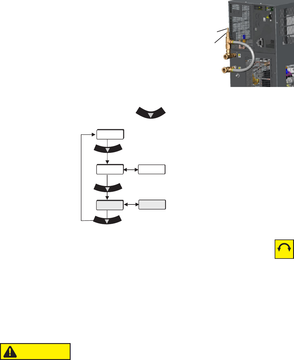
Use the pressure relief valve to set the desired
system back pressure (P1) to your application. The
valve is factory preset to 80 ± 5 psi (5.5 ± 0.4 bar).
The valve's inlet/outlet
connections are ½"FNPT.
If the chiller is not plumbed to an application, set the
pressure by installing a loop of hose equipped
with a shut-off valve between the supply and
return ttings. Start the chiller and allow it to
prime, then close the valve.
Use the controller's to display P 1, it should display 80 ± 5 psi.
Packing Nut
Adjusting Screw
Figure 5-6 Nut and Screw
Use a screwdriver to turn the adjusting screw (counterclockwise to
reduce pressure) until the controller displays the desired setting.
Note Due to internal back pressure, the minimum pressure setting for a
deadheaded P 2 pump is 40 psi (2.8 bar), and 22 psi (1.5 bar) for a P 1 (these
settings prohibit external ow from the chiller).
If the chiller is plumbed to an application, ensure the chiller is off. Then back out
the adjusting screw counterclockwise to reduce pressure. Turn the chiller
on. Ensure that there is back pressure in the system. Turn the adjusting
screw until the controller displays the desired setting.
Do not exceed 100 psi (6.9 bar).
When complete, inspect the area around the
5
/
8
" packing nut for uid leaks.
If uid is present, slightly tighten the nut and reinspect.
P1
FLo
xx.x C
80
xx
-+
PSI/KPa
CAUTION
Section 5
ThermoFlex 5-5
Thermo Scientific
Flow Control with
Flow Readout
P 1 P 2 T 0 T 1 Pump
Pressure Relief with
Flow Readout
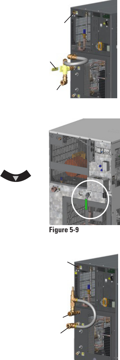
Figure 5-8 Flow Control
Figure 5-9 Flow Control
Handle (Typical)
Figure 5-10 Pressure Relief
Auxillary
Process
Outlet
Drain
Plug
Valve
Handle
Flow control for P 1, P 2, T0 and T 1 pumps on
ThermoFlex900 - 5000s is achieved using a 3-way
valve plumbed between the standard process
outlet and the process inlet on the rear of the
chiller. Use the auxiliary process outlet at the
top left of the rear of the chiller as a
connection point. The connections are ½"
FNPT. See Figure 5-8.
ThermoFlex3500 and 5000s with P 3 and P 4
pumps use a 2-way valve located on the rear
of the chiller. The connections are 3/4" FNPT.
See Figure 5-9.
ThermoFlex7500 and 24000s with P 2 - P 5 and
T 5 pumps (see next page) use a valve located
on the rear of the chiller. The connections are
1/2" FNPT for P 2, 1" FNPT for P 3 and P 5.
See Figure 5-9.
Press the controller's down arrow
twice to display the controller's FLo display, see
previous page. Turn the valve handle until the
desired rate is displayed.
Note The valve is sensitive to slight
adjustments.
Auxiliary
Process
Outlet
Process
Inlet
Process
Inlet
The Pressure Relief with Flow Readout
works just like the Pressure Relief Valve
discussed on the previous page. It allows
you to control the pressure going to your
application.
This valve is plumbed between the standard
process outlet and the process inlet on
the rear of the chiller. Use the auxiliary
process outlet at the top left of the rear of
the chiller as a connection point, allowing
you to also monitor the ow rate to your
application using the controller's FLo
display, see previous page.
The valve's outlet connection is ½" FNPT.
See Figure 5-10.