ThermoFlex-Manual.pdf - 第76页
Section 5 5-6 ThermoFlex Thermo Scientific Compliance SEMI c hill ers are compliant with: SEMI S2-0703 Product Safety Assessment SEMI S8-0705 Ergonomic Assessment SEMI S14-0704 Fire Risk Assessment SEMI F47-0706 Emergency…
Section 5
ThermoFlex 5-5
Thermo Scientific
Flow Control with
Flow Readout
P 1 P 2 T 0 T 1 Pump
Pressure Relief with
Flow Readout
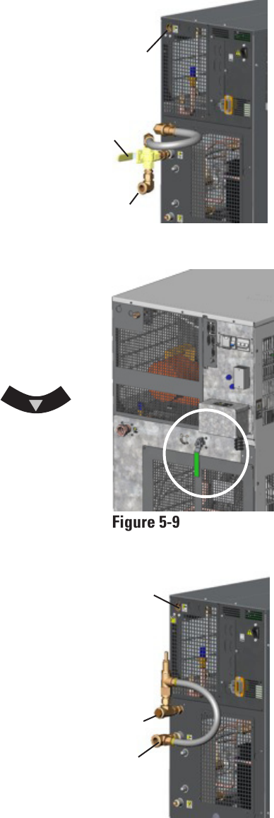
Figure 5-8 Flow Control
Figure 5-9 Flow Control
Handle (Typical)
Figure 5-10 Pressure Relief
Auxillary
Process
Outlet
Drain
Plug
Valve
Handle
Flow control for P 1, P 2, T0 and T 1 pumps on
ThermoFlex900 - 5000s is achieved using a 3-way
valve plumbed between the standard process
outlet and the process inlet on the rear of the
chiller. Use the auxiliary process outlet at the
top left of the rear of the chiller as a
connection point. The connections are ½"
FNPT. See Figure 5-8.
ThermoFlex3500 and 5000s with P 3 and P 4
pumps use a 2-way valve located on the rear
of the chiller. The connections are 3/4" FNPT.
See Figure 5-9.
ThermoFlex7500 and 24000s with P 2 - P 5 and
T 5 pumps (see next page) use a valve located
on the rear of the chiller. The connections are
1/2" FNPT for P 2, 1" FNPT for P 3 and P 5.
See Figure 5-9.
Press the controller's down arrow
twice to display the controller's FLo display, see
previous page. Turn the valve handle until the
desired rate is displayed.
Note The valve is sensitive to slight
adjustments.
Auxiliary
Process
Outlet
Process
Inlet
Process
Inlet
The Pressure Relief with Flow Readout
works just like the Pressure Relief Valve
discussed on the previous page. It allows
you to control the pressure going to your
application.
This valve is plumbed between the standard
process outlet and the process inlet on
the rear of the chiller. Use the auxiliary
process outlet at the top left of the rear of
the chiller as a connection point, allowing
you to also monitor the ow rate to your
application using the controller's FLo
display, see previous page.
The valve's outlet connection is ½" FNPT.
See Figure 5-10.
Section 5
5-6 ThermoFlex
Thermo Scientific
Compliance
SEMI chillers are compliant with:
SEMI S2-0703 Product Safety Assessment
SEMI S8-0705 Ergonomic Assessment
SEMI S14-0704 Fire Risk Assessment
SEMI F47-0706
Emergency Off (EMO)
A guarded red mushroom shaped push-button switch with twist-to-reset is
provided on the chiller's front to turn it off in case of an emergency. The
button head is engraved with “EMO” in large white lled letters.
Note The EMO is controlled by a safety circuit and is not inuenced by
the chiller's rmware/software.
Activation of the EMO button will remove power from the main contactor
coil stopping operation of the chiller. The controller will display Er 48.
Resetting the EMO button will not restart the chiller. After all hazards have
been removed reset the chiller by pushing the enter key on the controller.
In the local mode, the chiller will restart by pressing the START STOP
button again. In the serial communications mode, send the appropriate
start command. In the analog I/O mode, the chiller starts when the error is
cleared.
Chiller Circuit Breaker Interrupt Rating
The main power circuit breaker located on the rear of the chiller has an
Interrupting Capacity (AIC) of 10,000 amps.
Semiconductor
Equipment and
Materials
International
(SEMI)
Chillers
(ThermoFlex900-10000
only)
Chillers installed below the end-user application may allow system uid to
drain back into the chiller and cause spillage. The anti-drainback valve is
designed to prevent any such spillage.
The valve opens just before the pump is turned on and it closes just after
the pump shuts off.
This option is required if your chiller is more than 24 feet below your
application, or if there is a possibility of drain back due to the opening of
the process lines for either application swaps or chiller servicing.
Anti-Drainback
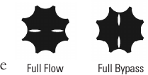
T 5 Pump Flow
Control
T 5 Flow Control valve is designed with slots to
quickly identify its position. When the slots are in the
horizontal position (in line with the discharge line)
the application is receiving full ow. With the slots are
vertical the valve is in full bypass.
Full Flow Full Bypass
Section 5
ThermoFlex 5-7
Thermo Scientific
A
B
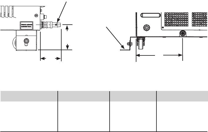
1/4 Turn Quick Disconnect Drip Pan Drain Fitting
C
Barb for
1/2" ID
Hose
900/1400 2500 3500/5000 7500/10000
A 3
1
/
2
" 8.8 cm 4" 10.1 cm 3
3
/
8
" 11.3 cm 4
1
/
4
" 10.8 cm
B 2
3
/
4
" 7.0 cm 2
11
/
16
" 6.8 cm 2
3
/
4
" 7.1 cm 2
5
/
8
" 6.6 cm
C 6
15
/
16
" 17.7 cm 6
9
/
16
" 16.7 cm 9
9
/
16
" 24.3 cm 7
11
/
16
" 19.5 cm
Figure 5-11 Drip Pan Drain
Seismic Tie-down
(typical)
Lockout/Tagout (LOTO)
Before performing Chiller maintenance, the energy sources associated with
the Chiller system must be lockedout and tagged out (LOTO). Hazard
control features added to the system (e.g., safety interlocks, EMO) are not a
substitute for turning off and locking out electrical or uid energy.
For chillers rated 20 Amps or less, electrical LOTO is accomplished by
removing the power cord on the rear of the chiller then closing and locking
the power receptacle locking device. For other chillers, electrical LOTO is
the responsibility of the user and can be provided by:
• Using the main disconnect (knife switch at system control cabinet).
• Disconnecting main power at the facility power source prior to the
system controller cabinet.
• In addition, follow all OSHA and local facility LOTO directives.
Drip Pan and Drain
The chiller is equipped with a secondary containment (drip pan) in case
there is a leak. The drip pan drain is located on the rear of the chiller.
Install the supplied nylon 1/4 turn quick disconnect (QD) tting into the
drain tting. The QD is barbed for a 1/2" ID hose.
Since the drip pan will not hold more than 110% of the reservoir volume,
connect the drain to guide the uid to an appropriate spillage location.