ThermoFlex-Manual.pdf - 第78页
Section 5 5-8 ThermoFlex Thermo Scientific D A B C Front View Side View 900/1400 2500 3500/5000 7500/10000 A 2 11 / 16 " 6.8 cm 2 11 / 16 " 6.8 cm 2 11 / 16 " 6.8 cm 2" 5.1 cm B* 18 ½ " 47.0 cm 20…
Section 5
ThermoFlex 5-7
Thermo Scientific
A
B
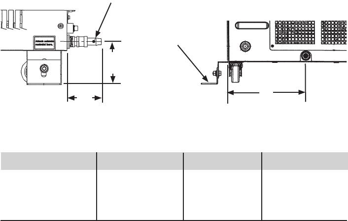
1/4 Turn Quick Disconnect Drip Pan Drain Fitting
C
Barb for
1/2" ID
Hose
900/1400 2500 3500/5000 7500/10000
A 3
1
/
2
" 8.8 cm 4" 10.1 cm 3
3
/
8
" 11.3 cm 4
1
/
4
" 10.8 cm
B 2
3
/
4
" 7.0 cm 2
11
/
16
" 6.8 cm 2
3
/
4
" 7.1 cm 2
5
/
8
" 6.6 cm
C 6
15
/
16
" 17.7 cm 6
9
/
16
" 16.7 cm 9
9
/
16
" 24.3 cm 7
11
/
16
" 19.5 cm
Figure 5-11 Drip Pan Drain
Seismic Tie-down
(typical)
Lockout/Tagout (LOTO)
Before performing Chiller maintenance, the energy sources associated with
the Chiller system must be lockedout and tagged out (LOTO). Hazard
control features added to the system (e.g., safety interlocks, EMO) are not a
substitute for turning off and locking out electrical or uid energy.
For chillers rated 20 Amps or less, electrical LOTO is accomplished by
removing the power cord on the rear of the chiller then closing and locking
the power receptacle locking device. For other chillers, electrical LOTO is
the responsibility of the user and can be provided by:
• Using the main disconnect (knife switch at system control cabinet).
• Disconnecting main power at the facility power source prior to the
system controller cabinet.
• In addition, follow all OSHA and local facility LOTO directives.
Drip Pan and Drain
The chiller is equipped with a secondary containment (drip pan) in case
there is a leak. The drip pan drain is located on the rear of the chiller.
Install the supplied nylon 1/4 turn quick disconnect (QD) tting into the
drain tting. The QD is barbed for a 1/2" ID hose.
Since the drip pan will not hold more than 110% of the reservoir volume,
connect the drain to guide the uid to an appropriate spillage location.
Section 5
5-8 ThermoFlex
Thermo Scientific
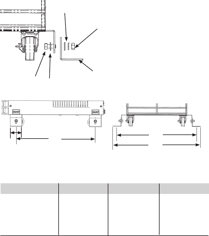
D
A
B
C
Front View
Side View
900/1400 2500 3500/5000 7500/10000
A 2
11
/
16
" 6.8 cm 2
11
/
16
" 6.8 cm 2
11
/
16
" 6.8 cm 2" 5.1 cm
B* 18 ½ " 47.0 cm 20
1
/
16
" 51.0 cm 24 ½" 62.2 cm 17" 43.1 cm
C* 19
11
/
16
" 50.0 cm 22
3
/
4
" 57.8 cm 24
3
/
4
" 62.9 cm 27
7
/
16
" 69.6
D 21
3
/
16
" 53.8 cm 24
1
/
4
" 61.5 cm 26
1
/
4
" 66.7 cm 28
15
/
16
" 73.4
* Distance between Ø.53 Seismic mounting holes
Figure 5-12 Seismic Tie-Downs
5/16" Bolt
5/16" Nut
5/16" Washer
5/16" Washers
Seismic Tie-Downs
Install the seismic tie-downs to the chiller as shown below. Then secure the
chiller to the oor with user-supplied hardware.
Seismic Tie-down (typical)
Section 5
ThermoFlex 5-9
Thermo Scientific
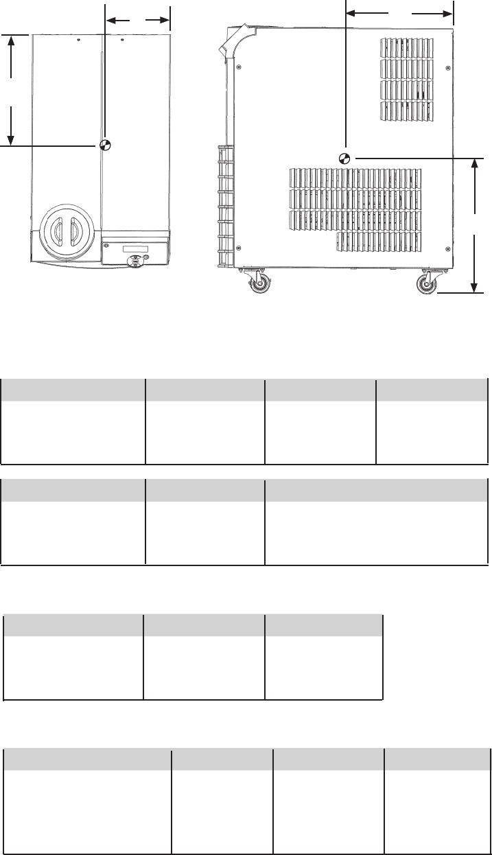
Center of Gravity ± ½", air-cooled chiller, no uid in tank
Center of Gravity ± ½", water-cooled chiller, no uid in tank
Top View
A
A
B
C
Side View
Figure 5-13 Center of Gravity
900/1400 P2 Pump 2500 P2 Pump 3500/5000 P2 Pump 7500/10000 P3 Pump
A 10
3
/
4
" 27.3 cm 12" 30.5 cm 13
3
/
8
" 34.0 cm 14
7
/
8
" 37.8 cm
B 6
3
/
4
" 17.2 cm 8
3
/
8
" 21.3 cm 9" 22.9 cm 13
1
/
8
" 33.3 cm
C 13
1
/
2
" 34.3 cm 13
1
/
2
" 34.3 cm 17" 43.2 cm 26" 66.0 cm
20000 P3 Pump 24000 P3 Pump 5000 P4 Pump Global Voltage
A 13
3
/
4
" 34.9 cm 12" 30.5 cm 12
3
/
8
" 31.4 cm
B 21
5
/
8
" 54.9 cm 8
3
/
8
" 21.3 cm 9
3
/
4
" 24.8 cm
C 21
1
/
4
" 54.0 cm 13
1
/
2
" 34.3 cm 19
1
/
2
" 49.5 cm
5000 P2 Pump 20000 P3 Pump 24000 P3 Pump
A 13" 33.0 cm 17" 43.2 cm 12" 30.5 cm
B 9
1
/
2
" 24.1 cm 22" 55.9 cm 23" 58.4 cm
C 16" 40.6 cm 20
1
/
2
" 52.1 cm 21" 53.3 cm
900/1400 P2 2500 P2 3500/5000 P2 7500/10000 P3
Left Front 27.1 lbs 12.3 kg 40.7 lbs 18.5 kg 62.0 lbs 28.1 kg 97.8 lbs 44.4 kg
Left Rear 29.8 lbs 13.5 kg 42.0 lbs 19.1 kg 63.7 lbs 28.9 kg 99.9 lbs 45.3 kg
Right Front 32.9 lbs 14.9 kg 45.7 lbs 20.7 kg 68.2 lbs 30.9 kg 89.2 lbs 40.5 kg
Right Rear 36.2 lbs 16.4 kg 47.1 lbs 21.4 kg 70.0 lbs 31.8 kg 91.1 lbs 41.3 kg
Center of Gravity
Weight Distribution ± 2 lbs, air-cooled chillers