ThermoFlex-Manual.pdf - 第98页
Section 7 7-10 ThermoFlex Thermo Scientific Checklist Chiller will not star t Check electrical connections . F or rst time use, please refer to the quic k star t instr uctions included with your c hiller or the copy in t…
Thermo Scientic ThermoFlex 7-9
Section 7
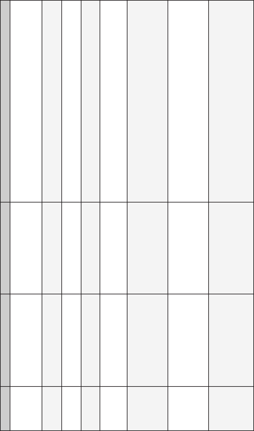
Error Code Reaction Cause Actions
Er 41
Chiller continues to run. Momentary communication
error between display and
main control board.
•Cycle circuit protector on rear of chiller off and on,
ThermoFlex900-10000 only.
Er 42
Chiller continues to run. Momentary internal
communications error.
•Contact our Sales, Service and Customer Support.
Er 47
Chiller will shut down. Chiller’s optional remote
EMO button depressed.
•When able, reset the EMO.
Er 48
Chiller will shut down.
(Optional display.)
Chiller’s optional EMO
button depressed.
•When able, reset the EMO.
Er 59
Chiller will shut down. Invalid level fault. Chiller
sensed both a high level and
low level reservoir uid level.
•Contact our Sales, Service and Customer Support.
Er 62
Chiller will not start.
(Chillers equipped with
optional Analog I/O.)
Probe not properly
connected.
Shorted remote temperature
probe.
•Check connection.
Er 63
Chiller will not start.
(Chillers equipped with
optional Analog I/O.)
Probe not properly
connected.
Open remote temperature
probe.
•Check connection.
Er 64
Chiller will continue to run
Chiller the last valid setpoint
received.
(Chillers equipped with
optional Analog I/O.)
Analog remote setpoint
is enabled and the chiller
receives a voltage or current
level that is outside the
chiller’s set point range.
• The error can be cleared only after a valid set point is received, or
the remote analog setpoint is turned off.

Section 7
7-10 ThermoFlex
Thermo Scientific
Checklist
Chiller will not start
Check electrical connections.
For rst time use, please refer to the quick start instructions included
with your chiller or the copy in this manual. The manual's copy follows
the Table of Contents.
Check the controller for error codes, see Error Codes in this Section.
Ensure the optional GFCI breaker located on the rear of the chiller is
in the up position.
For ThermoFlex900 - 10000 chillers ensure the circuit protector is in the
on ( I ) position.
Make sure supply voltage is connected and matches the chiller's
nameplate rating ±10%
No display on controller or display is 8888
For ThermoFlex900 - 10000 recycle the circuit protector on the rear of
the chiller.
Clearing Error Codes
Note the code in case it clears before you are done troubleshooting.
If desired, silence the audible alarm by pressing the up or down arrow
key.
If the chiller shut down, the controller will continue to ash the error code.
Press enter to clear the display and silence any alarm. Refer to Error
Codes in this Section. Once the cause of the shut down is identied
and corrected, start the chiller. If the cause was not corrected the error
code will reappear.
If the chiller is still running, press enter to see if the code clears, a limit
may have been only temporarily exceeded. If the error code does not
clear press
until the display ashes between the error code and
the temperature and then press enter. If the code still does not clear
refer to Error Codes in this Section.
Section 7
ThermoFlex 7-11
Thermo Scientific
Chiller shuts down
Ensure button wasn't accidently pressed.
Ensure the optional GFCI breaker located on the rear of the chiller is
in the up position.
For ThermoFlex900 - 10000 chillers ensure the circuit protector is in
the on ( I ) position.
Check the controller for error codes, see Error Codes in this Section.
The chiller is designed to shut down if not properly primed.
If able, pre-ll the process uid lines.
After start up continue adding process uid until the chiller and
uid lines are full.
If you need to pause chiller priming turn the chiller off using the
power button
on the front panel.
Not completely lling the chiller and process uid lines
could damage the chiller’s pump.
Make sure supply voltage is connected and matches the chiller's
nameplate rating ±10%.
Restart the chiller.
Chiller vibration
The optional pressure relief valve setting may be the cause. Change the
pressure setting ± 5 psi to eliminate the vibration.
Inadequate pump pressure
Ensure any user installed in-line valves are in the desired position.
Ensure the chiller’s process uid outlet is connected to the application’s
uid inlet and not the application’s uid outlet, see Section 3.
Ensure all connections are secure and that the proper sealant/lubricant
for the tting material is used.
Keep the distance between the chiller and the instrument being cooled
as short as possible.
Ensure tubing is straight and without bends. If diameter reductions are
required, make them at the inlet and outlet of your application, not at
the chiller.
CAUTION