PSV7000_ Owners Manual_096-0460-001B - 第101页
■ 3D Coplanarity Optio n ◘ 3D Inspection Results PSV7000 Owner’s Manual 3—31 back 8. If your job h as not been run before using the 3D Inspection Sys- tem, the P ackage File will need to be taught the location of the 3D …
Administrative Functions ■ 3D Coplanarity Option
3—30 Data I/O • 096-0460-001B
back
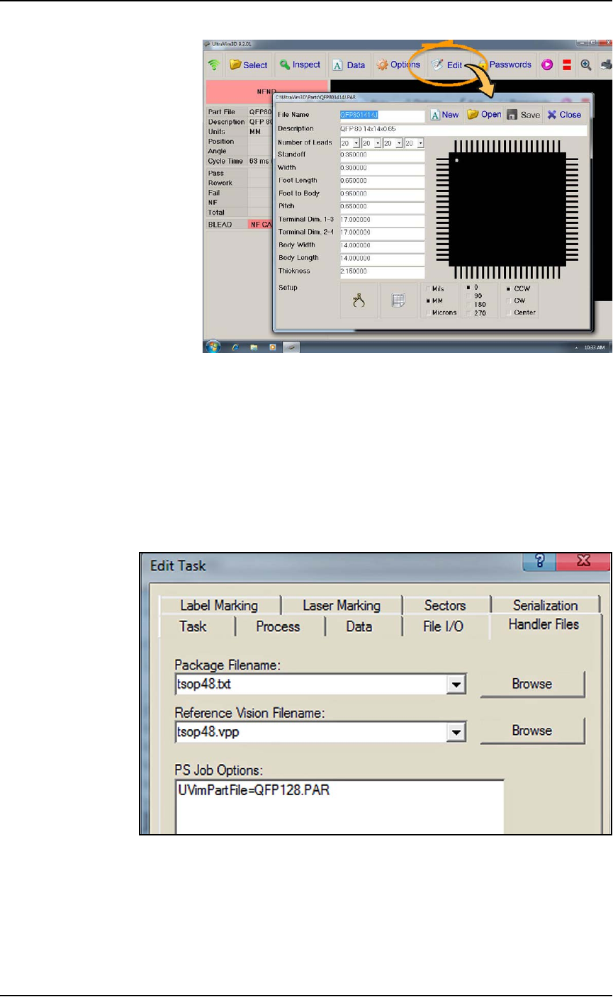
Figure 3-17: Adding or editing a device specifications file.
5. On the PSV7000 keyboard, push the monitor toggle sequence to
switch back to the PS Handler computer (scroll lock key twice
and then 1).
6. For the desired job in TaskLink, open the Edit Task dialog > Han-
dler Files tab. In the PS Job Options field, type in the name of the
device file you created; (the UltraVim manual terminology is
part file). These files are stored on the 3D Inspection System
computer.
Figure 3-18: : The PS Job Options field (TaskLink > Edit Task >
Handler Files) is an editor that you type into directly which passes
parameters to the AH700 Software.
7. Save the job.
■ 3D Coplanarity Option ◘ 3D Inspection Results
PSV7000 Owner’s Manual 3—31
back
8. If your job has not been run before using the 3D Inspection Sys-
tem, the Package File will need to be taught the location of the
3D Inspection System. (Refer to the AH700 on-screen Help for
similar edits to the Package, such as teaching a tray location.
9. Run your job.
Note: Typical AH700 options are available such as the
Ignore Pro-
grammers
feature (on the Options tab) if 3D inspection only is
desired without programming devices.
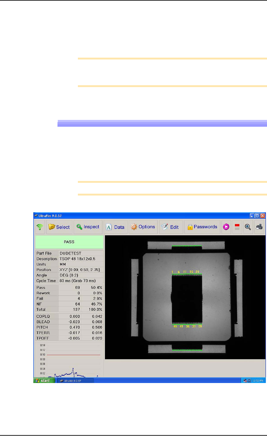
3D Inspection Results
For each device inspected, UltraVim displays an image of the device
as well as a graph and other data.
A good inspection image displays all green dots on the all the leads.
See the two images below.
Note: Specifications for Rework and Fail can be edited.
Figure 3-19: A good inspection image. The dot at each lead is green.
Administrative Functions ■ 3D Coplanarity Option
3—32 Data I/O • 096-0460-001B
back
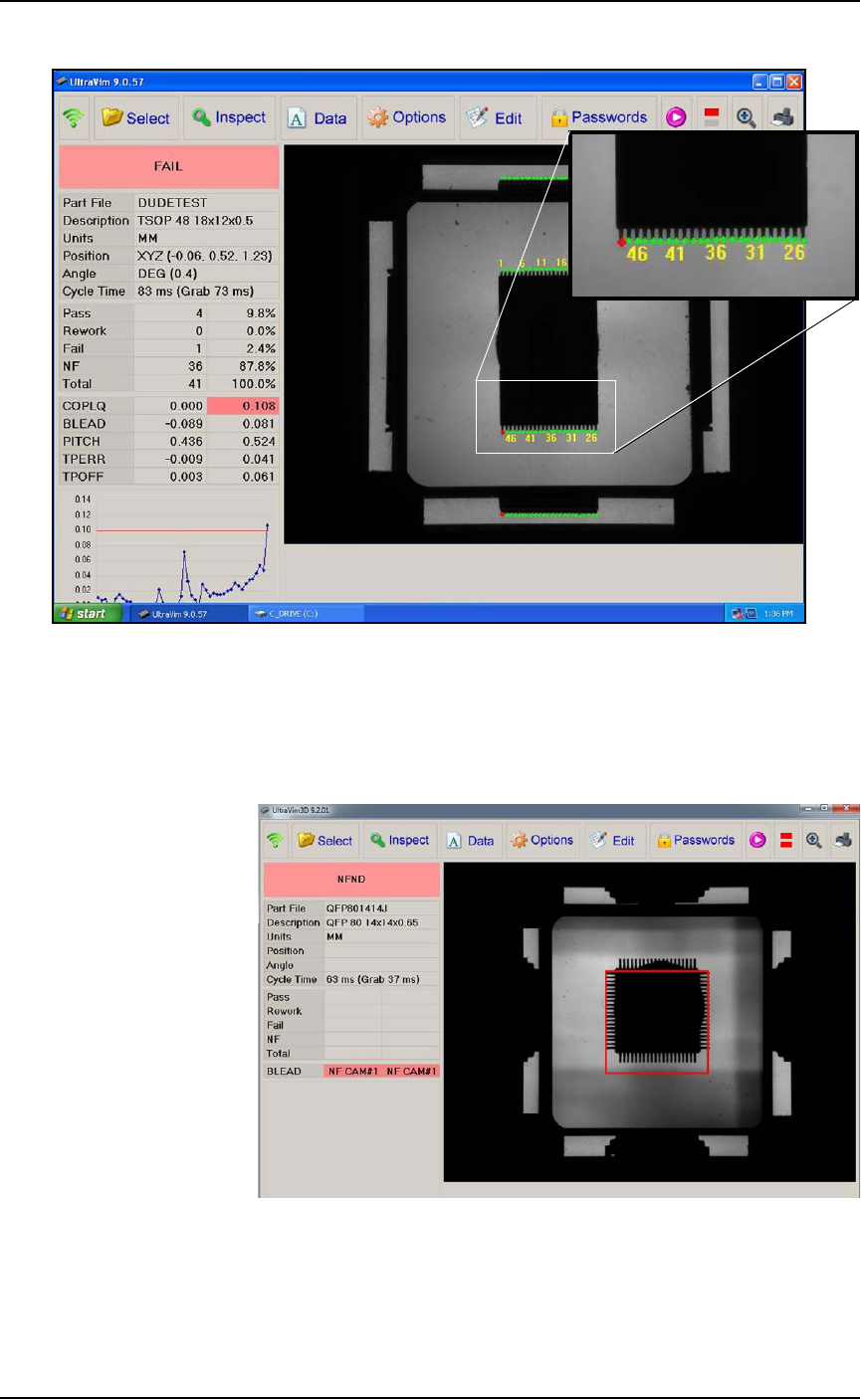
Figure 3-20: This inspection image shows 1 lead failed (see the red
dot).
3D Troubleshooting
Probe goes down too low.
Figure 3-21: Probe is too low: you can see the probe tip all four of the
side views.
Resolution: Adjust the Z-height in AH700.