PSV7000_ Owners Manual_096-0460-001B - 第116页
Maintenance ■ Workspace, Head and Gantry 4—10 Data I/O • 096-0640-001B back 3. At the Actuator Ta b , c l i c k Actuate Socket ON and OFF to visually verify performance for refe rence. Figure 4-2: The Socket Opener P res…
■ Workspace, Head and Gantry ◘ Socket Adapters and Actuation
PSV7000 Owner’s Manual 4—9
back
Turning OFF Input Air
Prior to turning off the input air, ensure that no job is running.
CAUTION: Possible damage to programmers and devices! DO
NOT TURN AIR OR POWER OFF to the PSV7000 Machine while
a job is running.
A job must be
Finished
before turning OFF compressed air or elec-
trical power. Wait for the gantry to park before turning OFF.
1. If a job is running, Pause or Finish it.
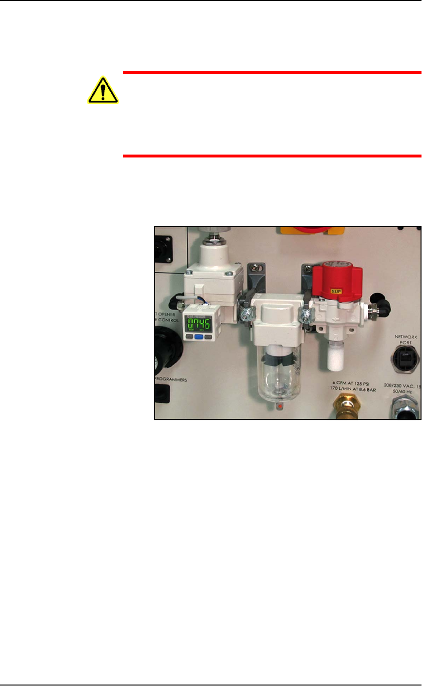
2. On the Power Panel, rotate the valve clockwise to turn OFF the
input air; it is off when the lock rings line up. See Figure 4-1.
Figure 4-1: The input air regulator/filter on the Power Panel (on the left
side of the machine). When the lock rings on the valve line up, the air
supply to the PSV7000 Machine is OFF.
3. (Optional) Paddle lock the air shutoff valve.
Adjusting the Socket Actuator Air Pressure on the
Programmers
Socket Actuators are built into the FlashCORE programmers on
PSV7000. Socket actuation is controlled by air pressure. If Socket
Actuators are slamming up and down loudly, or devices are
bouncing, the air pressure may be too high. If the PNP head does not
properly pick or place a device in a socket because the socket is not
opening completely, the air pressure might be set too low.
Adjust the air pressure setting as follows:
1. Finish a job if one is running.
2. Navigate to the Gantry window and click the yellow label for a
programmer that is easy to see.
Maintenance ■ Workspace, Head and Gantry
4—10 Data I/O • 096-0640-001B
back
3. At the Actuator Tab, click Actuate Socket ON and OFF to visually
verify performance for reference.
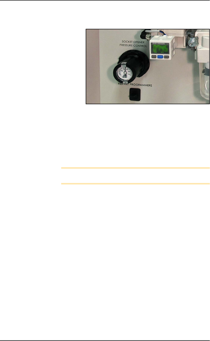
Figure 4-2: The Socket Opener Pressure Control knob with built-in
gauge on the Power Panel.
4. At the Power Panel on the left side, adjust the air pressure up or
down as desired by pulling the collar on the black knob out and
then rotating it.
5. Push the collar back in.
6. Actuate the socket as before to verify the change in action.
7. Repeat if necessary.
Note: If Socket Actuator problems persist, set the actuator speed
(refer to the next heading).
Adjusting the Socket Actuator Speed on the
Programmers
THE SOCKET ACTUATOR SPEED WAS SET AT THE FACTORY
AND SHOULD NOT NEED ADJUSTMENT. If it is determined that
adjustment is necessary, this procedure requires a Data I/O trained
technician since it requires having an access door open while the
machine power is on.
Requirements
• Programmer air pressure must be correct. See previous heading.
• Small flat screw driver.
To adjust the speed of the Socket Actuators:
1. Ensure that power and air are connected and ON, and a Socket
Adapter is installed on the target programmer.
2. At the Gantry window, click the label for a programmer with the
adapter installed. Probe 1 will stop over socket 1.
■ Workspace, Head and Gantry ◘ Socket Adapters and Actuation
PSV7000 Owner’s Manual 4—11
back
WARNING: Electric shock hazard! Opening any access doors
while the power is ON can be dangerous even when steps
instruct you to do so. Use extreme caution and do not touch
any electronic equipment except as directed.
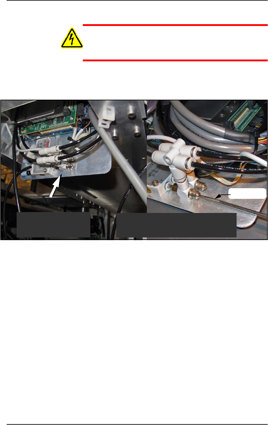
3. Open the access door nearest the target programmer and locate
the in-line air flow control for the up (sockets closed) position.
Refer to Figure 4-3.
Figure 4-3: Actuator flow controls (arrow). The lower one (that the
screwdriver is at) sets the UP speed.
4. Adjust the appropriate flow control 1/2 to 1 revolution clockwise
for slower action, or counter-clockwise for faster action.
5. Close the access door, and clear the door open warning on the
monitor.
6. At the Actuate tab of the Gantry window, click the Actuate Socket
switch to ON while listening and watching the opener.
If it is too fast it will produce a louder noise than optimum when
it operates. If it is too slow it will look slow.
7. Click Actuate Socket OFF.
8. Adjust the flow controls as necessary and repeat the test.
9. Perform the same procedure for the other flow control if neces-
sary.
Looking upward inside
the access door.
Looking upward inside
the access door.
Shown here with programmer removed
for illustration purposes only.
screwdriver