PSV7000_ Owners Manual_096-0460-001B - 第117页
■ Workspace, Head and Gantry ◘ Socket Adapters and Actuation PSV7000 Owner’s Manual 4—11 back WARNING: Electric shock ha zard! Opening any access doors while the power is ON can be dangerous eve n when steps instruct you…
Maintenance ■ Workspace, Head and Gantry
4—10 Data I/O • 096-0640-001B
back
3. At the Actuator Tab, click Actuate Socket ON and OFF to visually
verify performance for reference.
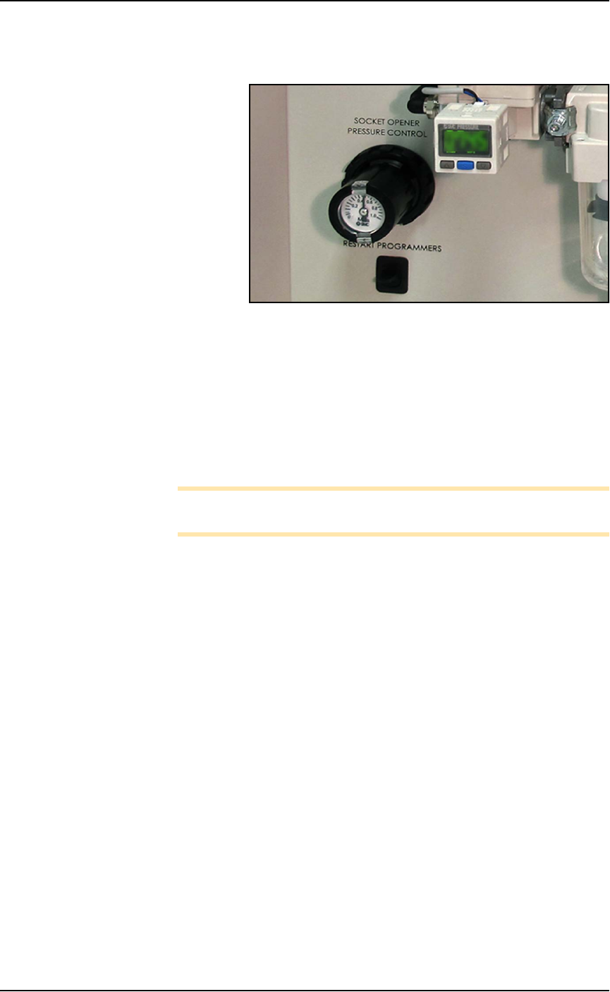
Figure 4-2: The Socket Opener Pressure Control knob with built-in
gauge on the Power Panel.
4. At the Power Panel on the left side, adjust the air pressure up or
down as desired by pulling the collar on the black knob out and
then rotating it.
5. Push the collar back in.
6. Actuate the socket as before to verify the change in action.
7. Repeat if necessary.
Note: If Socket Actuator problems persist, set the actuator speed
(refer to the next heading).
Adjusting the Socket Actuator Speed on the
Programmers
THE SOCKET ACTUATOR SPEED WAS SET AT THE FACTORY
AND SHOULD NOT NEED ADJUSTMENT. If it is determined that
adjustment is necessary, this procedure requires a Data I/O trained
technician since it requires having an access door open while the
machine power is on.
Requirements
• Programmer air pressure must be correct. See previous heading.
• Small flat screw driver.
To adjust the speed of the Socket Actuators:
1. Ensure that power and air are connected and ON, and a Socket
Adapter is installed on the target programmer.
2. At the Gantry window, click the label for a programmer with the
adapter installed. Probe 1 will stop over socket 1.
■ Workspace, Head and Gantry ◘ Socket Adapters and Actuation
PSV7000 Owner’s Manual 4—11
back
WARNING: Electric shock hazard! Opening any access doors
while the power is ON can be dangerous even when steps
instruct you to do so. Use extreme caution and do not touch
any electronic equipment except as directed.
3. Open the access door nearest the target programmer and locate
the in-line air flow control for the up (sockets closed) position.
Refer to Figure 4-3.
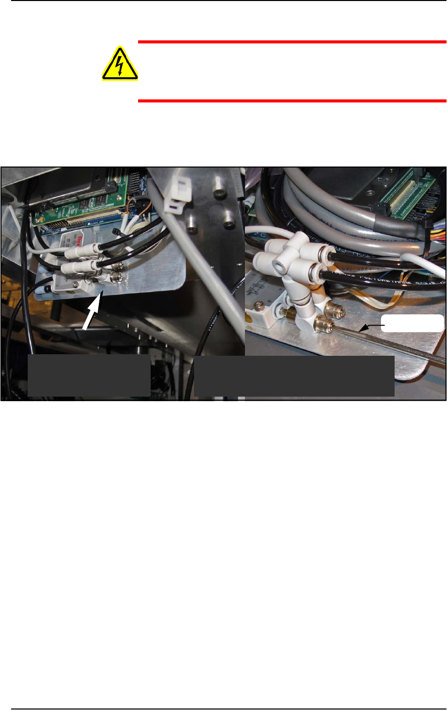
Figure 4-3: Actuator flow controls (arrow). The lower one (that the
screwdriver is at) sets the UP speed.
4. Adjust the appropriate flow control 1/2 to 1 revolution clockwise
for slower action, or counter-clockwise for faster action.
5. Close the access door, and clear the door open warning on the
monitor.
6. At the Actuate tab of the Gantry window, click the Actuate Socket
switch to ON while listening and watching the opener.
If it is too fast it will produce a louder noise than optimum when
it operates. If it is too slow it will look slow.
7. Click Actuate Socket OFF.
8. Adjust the flow controls as necessary and repeat the test.
9. Perform the same procedure for the other flow control if neces-
sary.
Looking upward inside
the access door.
Looking upward inside
the access door.
Shown here with programmer removed
for illustration purposes only.
screwdriver
Maintenance ■ Workspace, Head and Gantry
4—12 Data I/O • 096-0640-001B
back
Cleaning the PSV7000 Machine
General Machine Cleaning
General cleaning should be performed on a weekly basis. General
cleaning includes, but is not limited to, the following listed item.
WARNING: Vision hazard! Pressurized air or debris blown
into the eyes or skin could cause bodily damage. Always use
care and wear protective eye goggles when cleaning with
pressurized air.
1. Remove all dropped devices, debris, and other materials from all
working areas.
2. With air and power OFF, remove all devices and materials that
may have fallen inside the machine.
3. Use dry, compressed air to remove all dust and debris from the
work surface and from under the machine.
4. Dust the safety doors, inside and outside, with an antistatic
cleaner.
5. Wipe the top and side panels to remove grease, fingerprints, and
dust.
6. Dust the top surfaces of the input/output modules.
Cleaning the Device Position Sensor
Fingerprints and excessive amounts of dust or other residue on the
optical windows of the Device Position Sensor will degrade the per-
formance of the sensor. The sensor is mounted on the bottom of the
PNP head.
If the sensors are not providing a good image, it may be an indicator
that the windows need cleaning.
For instructions to turn
OFF the air, see page
4-9.