PSV7000_ Owners Manual_096-0460-001B - 第121页
■ Workspace, Head and Gantry ◘ Adjusting Prob e Blow-Off Pressure PSV7000 Owner’s Manual 4—15 back Adjusting Probe Blow-Off Pressure Note: The flow controls ar e set at the factory and should not requir e adj ustment. If…

Maintenance ■ Workspace, Head and Gantry
4—14 Data I/O • 096-0640-001B
back
Pick and Place Probes
The workspace Pick and Place head has two probes which require
periodic maintenance. The headings below describe maintenance.
Checking the Probe Tips
Worn or damaged probe tips on the PNP head can cause dropped
devices and placement problems.
1. Check the probe tips for cracks or tears. If necessary, replace
with a probe tip of the same size.
2. Test the probe tip—
2a. At the Setup window, click System > Gantry.
2b. Click the Vacuum switch to ON.
2c. Open the safety door and place a device on the target probe.
2d. If the vacuum does not firmly hold the device, replace the
probe tip with a probe tip of the same size.
Checking the Probes
Check that each probe is not loose. Tighten the set screw on the stem
if necessary. If you suspect or hear an air leak (and your style of probe
has a set screw):
1. Remove the set screw on the probe stem.
2. Pull off the probe stem and check the O-ring. Replace if neces-
sary.
3. Reassemble.
Cleaning the Probe Tips
To clean the Probe tips:
1. Move the PNP head to a convenient position by clicking one of
the yellow labels on the Gantry window. The Tool position is rec-
ommended.
2. Open the safety door.
3. Wipe the tip
with alcohol wipes (Data I/O PN 570-0410-001) or a
damp cloth.
Note: Do not touch the probe tip with bare hands. Finger oils can
cause small devices to stick.
■ Workspace, Head and Gantry ◘ Adjusting Probe Blow-Off Pressure
PSV7000 Owner’s Manual 4—15
back
Adjusting Probe Blow-Off Pressure
Note: The flow controls are set at the factory and should not
require adjustment. If adjustments need to be made, they should be
done in small steps until the desired results are reached.
Blow-off is a small puff of air applied at the probes during the device
drop event to assist in removing a device from the probe. Blow-off is
produced by a vacuum generator on the PNP head. If set too high,
blow-off could cause device misalignment during placement.
Tools Required
• Large flat screwdriver
• Very small flat screwdriver
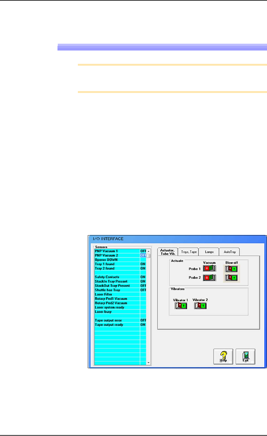
To adjust blow-off pressure on any vacuum generator:
1. Click System > Misc. I/O.
2. At the I/O Interface window, select the desired vacuum genera-
tor, probe 1 or probe 2 (or both).
3. Click Vacuum to the OFF position. Refer to Figure 4-5.
4. Click Blow-off to the ON position.
Figure 4-5: Vacuum and Blow-off on the I/O Interface window.
Maintenance ■ Workspace, Head and Gantry
4—16 Data I/O • 096-0640-001B
back
WARNING: Possible collision hazard! The high speed and
force of the gantry can seriously harm anyone working inside
the workspace.
When working within the machine workspace, moving the
PNP head must be the responsibility of only one qualified
individual. All others must stay clear of the machine controls
to prevent injury to that person.
Ensure that a job is Paused or Finished, or the system power
is OFF prior to opening any safety doors.
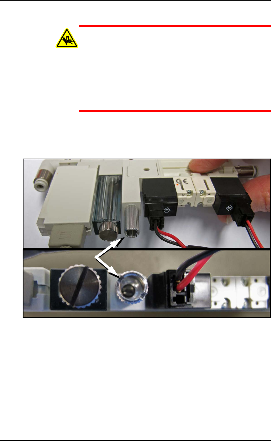
5. Locate the actual vacuum generator (Data I/O PN 815-0047-001+)
on the right side of the PNP head. Find the blow-off adjustment
set-screw. It is inside a long knurled stem which needs to be
loosened before adjusting the set-screw. See Figure 4-6.
Figure 4-6: The Blow-off adjustment set-screw on the vacuum
generator is inside a knurled locking stem (arrow). (The vacuum block
must NOT be removed as shown here.)
6. Turn the adjustment screw until the vacuum generator readout
displays +1.5 to 2.0 kPa.
7. While holding the set screw with the screwdriver, tighten the
knurled stem.
8. Do the same for the other probe.
9. Click Blow-off to the OFF position.
If you had a blow-off problem, test your results.