PSV7000_ Owners Manual_096-0460-001B - 第123页
■ Workspace, Head and Gantry ◘ Adjusting the Vacuum Gene rator Sensors PSV7000 Owner’s Manual 4—17 back Adjusting the V acuum Gener ator Sensors Note: If you notice consecuti ve pr ogramming pick err ors, before adjustin…
Maintenance ■ Workspace, Head and Gantry
4—16 Data I/O • 096-0640-001B
back
WARNING: Possible collision hazard! The high speed and
force of the gantry can seriously harm anyone working inside
the workspace.
When working within the machine workspace, moving the
PNP head must be the responsibility of only one qualified
individual. All others must stay clear of the machine controls
to prevent injury to that person.
Ensure that a job is Paused or Finished, or the system power
is OFF prior to opening any safety doors.
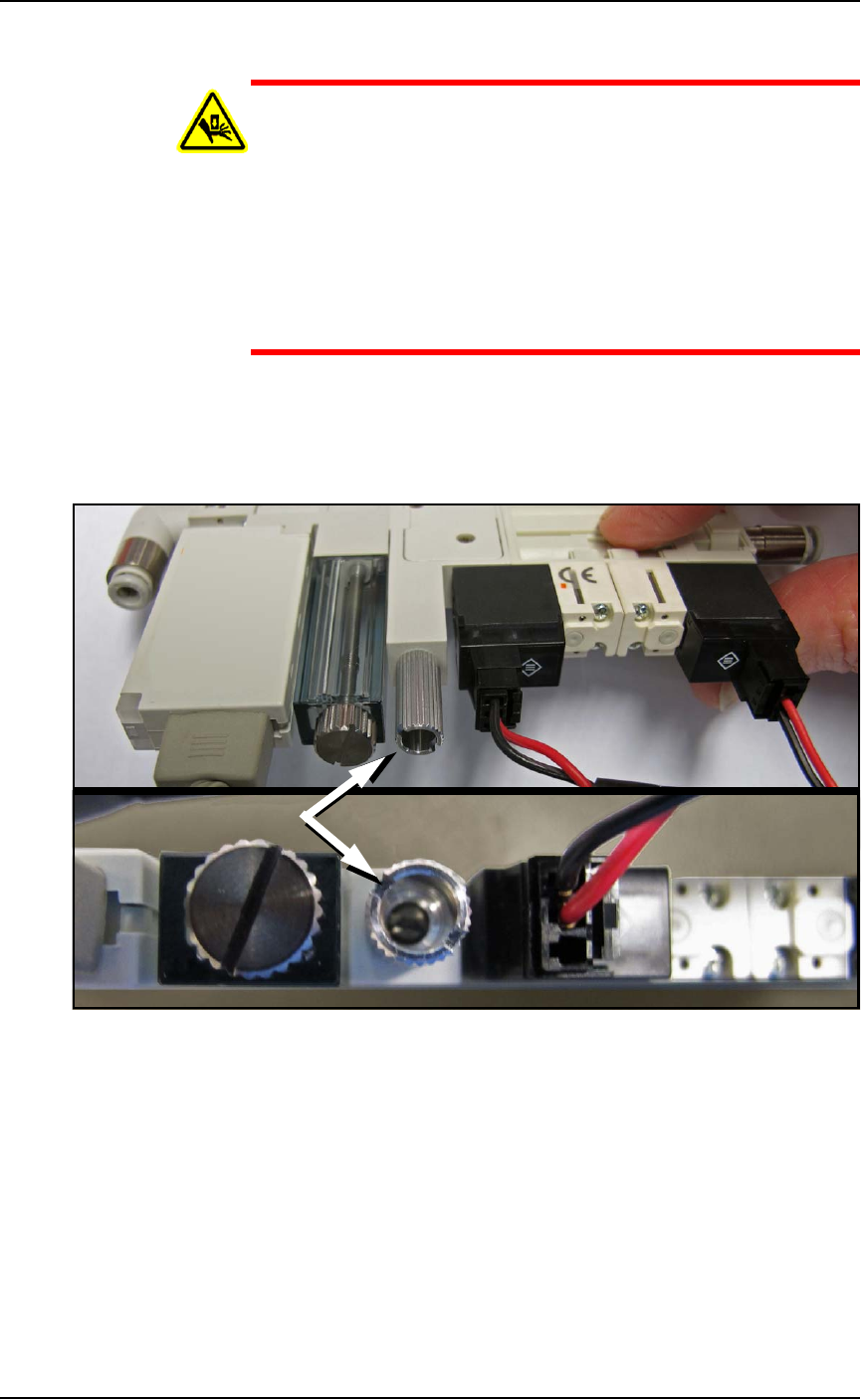
5. Locate the actual vacuum generator (Data I/O PN 815-0047-001+)
on the right side of the PNP head. Find the blow-off adjustment
set-screw. It is inside a long knurled stem which needs to be
loosened before adjusting the set-screw. See Figure 4-6.
Figure 4-6: The Blow-off adjustment set-screw on the vacuum
generator is inside a knurled locking stem (arrow). (The vacuum block
must NOT be removed as shown here.)
6. Turn the adjustment screw until the vacuum generator readout
displays +1.5 to 2.0 kPa.
7. While holding the set screw with the screwdriver, tighten the
knurled stem.
8. Do the same for the other probe.
9. Click Blow-off to the OFF position.
If you had a blow-off problem, test your results.
■ Workspace, Head and Gantry ◘ Adjusting the Vacuum Generator Sensors
PSV7000 Owner’s Manual 4—17
back
Adjusting the Vacuum Generator
Sensors
Note: If you notice consecutive programming pick errors, before
adjusting vacuum sensors complete the Z-Axis adjustment. For
instructions on Z-Axis adjustment, see Teaching the Workspace
Locations on page 3-9. If completing the Z-Axis adjustment does
not reduce or eliminate subsequent pick errors, complete the vac-
uum sensor adjustments described here.
Vacuum sensors on the PSV7000 System are adjustable. The
I/O Interface window displays a list of the sensors in the
PSV7000 System and the status of each sensor.
Note: The number of sensors on the PSV7000 System depends on
the options installed.
To view the status of sensors at the main AH700 Setup window, click
System > Misc. I/O.
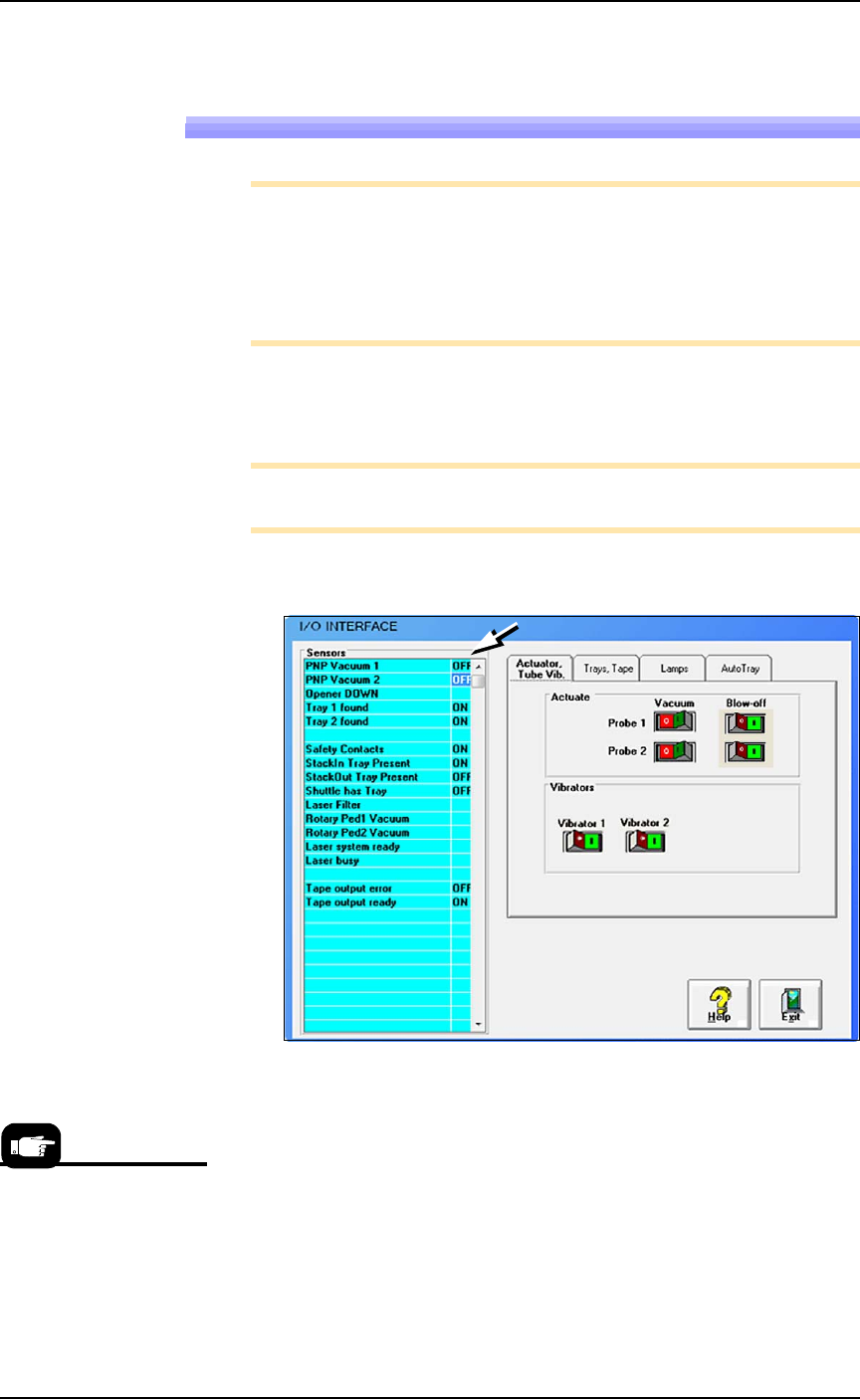
Figure 4-7: The I/O Interface window reports sensor status and allows
switching options on or off. (The number of tabs vary.)
To Adjust Probe Vacuum Generator Sensors:
1. Finish a job.
2. At the Gantry window, move the PNP head to the Tool position
3. Close the Gantry window and at the System window click
Misc. I/O.
4. At the I/O Interface tab, for both probes, click the Vacuum toggle
ON and the Blow-off toggle OFF. Refer to the figure above.
Click the Tool label on
the Gantry window to
move the head for easy
access; front and center.
Maintenance ■ Workspace, Head and Gantry
4—18 Data I/O • 096-0640-001B
back
5. Open the safety door.
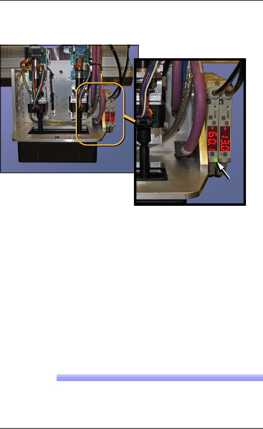
6. With a device or clean finger, plug probe tip 1 and ensure the
green generator lamp comes on. See Figure 4-8.
Figure 4-8: The PNP Probe vacuum generator adjustments. In this
image, the green lamp for probe #2 is ON.
7. Read the high and low values each time you plug the air with
your finger and release it. They are needed for the next step.
8. Set the trigger value on the sensor by pressing the S (blue SET)
button on the vacuum generator block and then using the UP or
DOWN buttons, set the value to midway between the high value
and the low value. It should be approximately -40 kPa.
9. Press the SET button again.
10. Check adjustment by blocking and unblocking the probe tip sev-
eral times and ensuring the green lamp goes on and off each
time.
11. Repeat these steps for probe 2.
12. Turn OFF the vacuum switches for both probes.
Wipe the probe tips with a clean dry cloth.
Replacing the Input Air Filter
1. If a job is running, Pause or Finish the job.