PSV7000_ Owners Manual_096-0460-001B - 第125页
■ Workspace, Head and Gantry ◘ Vacuum Generator Filters and Silencers PSV7000 Owner’s Manual 4—19 back 2. T urn off shop air and disconnect the input air line from the Air Fil- ter/Regulator at the quick connect fitting.…
Maintenance ■ Workspace, Head and Gantry
4—18 Data I/O • 096-0640-001B
back
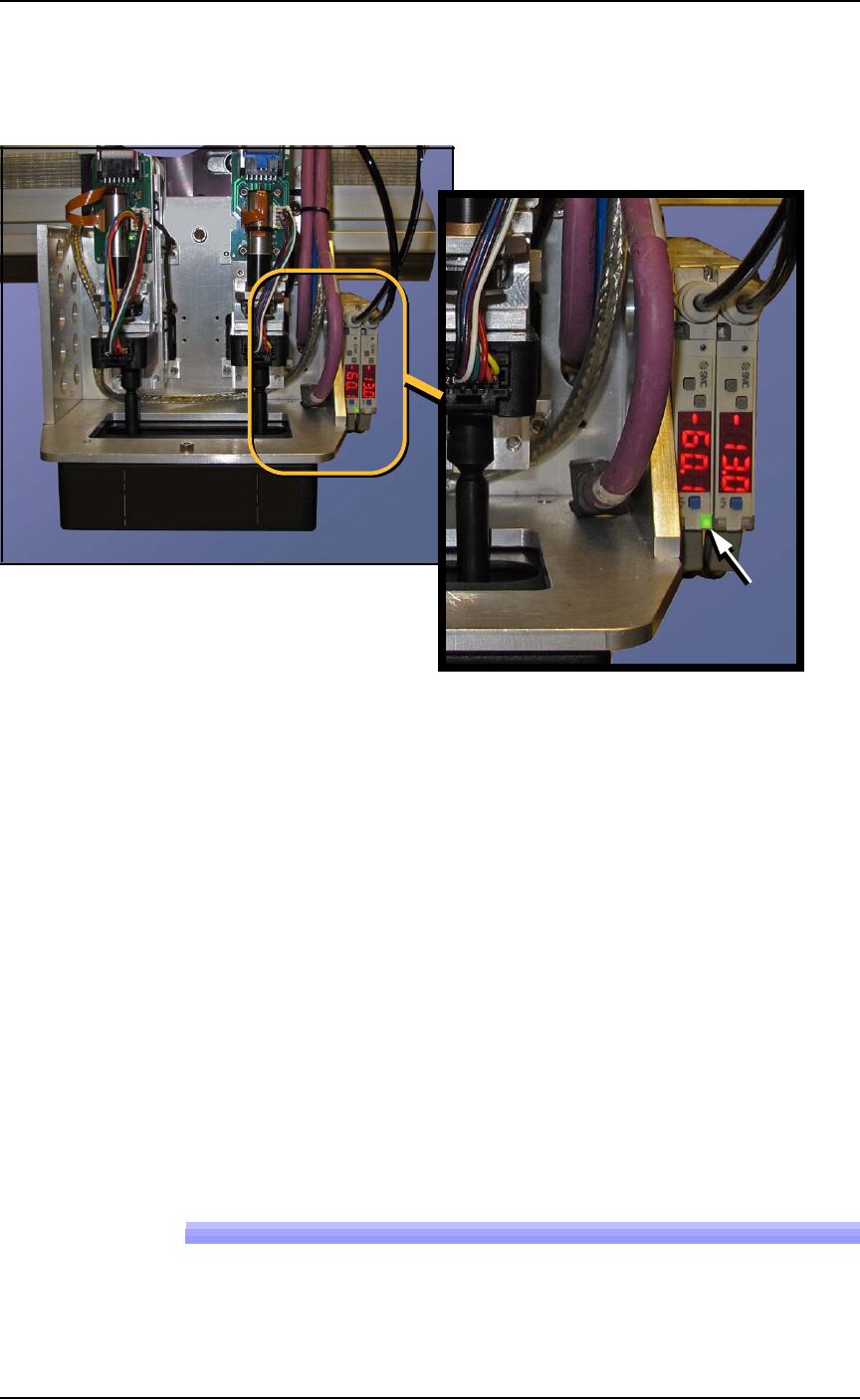
5. Open the safety door.
6. With a device or clean finger, plug probe tip 1 and ensure the
green generator lamp comes on. See Figure 4-8.
Figure 4-8: The PNP Probe vacuum generator adjustments. In this
image, the green lamp for probe #2 is ON.
7. Read the high and low values each time you plug the air with
your finger and release it. They are needed for the next step.
8. Set the trigger value on the sensor by pressing the S (blue SET)
button on the vacuum generator block and then using the UP or
DOWN buttons, set the value to midway between the high value
and the low value. It should be approximately -40 kPa.
9. Press the SET button again.
10. Check adjustment by blocking and unblocking the probe tip sev-
eral times and ensuring the green lamp goes on and off each
time.
11. Repeat these steps for probe 2.
12. Turn OFF the vacuum switches for both probes.
Wipe the probe tips with a clean dry cloth.
Replacing the Input Air Filter
1. If a job is running, Pause or Finish the job.
■ Workspace, Head and Gantry ◘ Vacuum Generator Filters and Silencers
PSV7000 Owner’s Manual 4—19
back
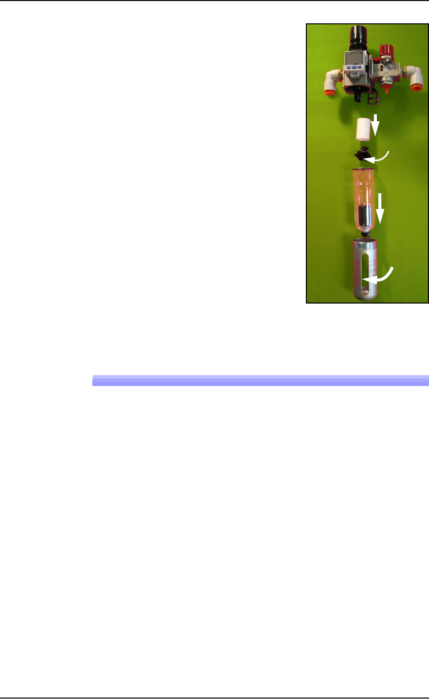
2. Turn off shop air and disconnect
the input air line from the Air Fil-
ter/Regulator at the quick connect
fitting.
3. Unscrew the air contamination
collection bowl housing.
4. Pull off the clear collection bowl.
Clean out any dirt, oil, or water.
5. Unscrew the black knob below the
filter.
6. Pull off the filter. Clean or replace
as necessary.
Reinstall in reverse order being careful
not to damage the O-ring on the bowl.
Reconnect the shop air supply line.
Figure 4-9: Replacing the Air Filter/Regulator.
Vacuum Generator Filters and Silencers
These procedures cover removing and cleaning or replacing vacuum
generator parts for vacuum generators on PSV7000 head.
A clogged or dirty vacuum filter or silencer can cause dropped
devices and placement problems at the PNP head.
Requirements
•metric hex key set
• flat screwdriver
• small Phillips screwdriver
Vacuum Generator Filters
1. Finish a job if one is running.
2. Use the Gantry window to move the PNP head to an accessible
location such as the Tool position.
3. Properly shut OFF the PSV7000 System. See Shutting Down the
PSV7000 System on page 2-7.
Filter
Knob
Bowl
Bowl
hous-
ing
In
Maintenance ■ Workspace, Head and Gantry
4—20 Data I/O • 096-0640-001B
back
WARNING: Shock hazard! Opening the safety doors stops
motion of the gantry only. It does not remove electrical
power from the machine or any optional equipment.
Turn the main power OFF for safety unless otherwise
directed.
4. Open the front safety door and mark the wire connectors at the
two vacuum pressure switches on the right side of the head for
returning them to the correct location.
5. For access, unplug the two wire connectors (just marked) by
pulling them out. See Figure 4-10 below.
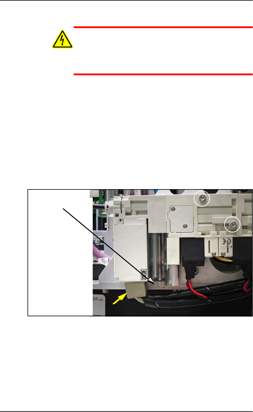
6. With a flat screwdriver, unscrew the knurled fastener on the
underside of the nearest filter housing. See the figure below.
7. Remove the filter housing and ensure that the o-ring doesn’t fall.
8. Remove the next housing.
9. Remove the filter from the each housing. They should be white
or nearly white. If dirty or clogged, replace with new filter
(Data I/O PN 294-0219-001+). See the figure below.
Figure 4-10: Removing the PNP head Vacuum Generator filter. The
filters are adjacent so only one is visible in this view. The yellow arrow
points to the wiring connectors.
Two fasteners attach the inner and outer pneumatic generator blocks
(circled).
Reinstall in reverse order and plug the two wire connectors back in at
the same locations.
Filter knob