PSV7000_ Owners Manual_096-0460-001B - 第129页
■ Workspace, Head and Gantry ◘ Gantry Belt Tension PSV7000 Owner’s Manual 4—23 back Figure 4-12: Grease fitting on the X-axis guide, shown. 5. Close the safety door . Gantry Belt T ension The Gantry drive belt may need t…
Maintenance ■ Workspace, Head and Gantry
4—22 Data I/O • 096-0640-001B
back
Inspecting Gantry Parts
Checking the PNP Head
1. Properly shut OFF the PSV7000 sub-systems and machine
power. Refer to Shutting Down the PSV7000 System on page 2-7.
2. Check that all connectors are secure.
3. Turn on the system air and check that there are no vacuum leaks.
Lubricating the Gantry
Requirements
• NSK Grease (Data I/O PN 560-0034-001) and Grease Gun MG70
(Data I/O PN 560-0035-001)
WARNING: Possible collision hazard! The high speed and
force of the gantry can seriously harm anyone working inside
the workspace.
When working within the machine workspace, moving the
PNP head must be the responsibility of only one qualified
individual. All others must stay clear of the machine controls
to prevent injury to that person.
Ensure that a job is Paused or Finished, or the system power
is OFF prior to opening any safety doors.
1. Move the PNP head to a programmer near the center of the
workspace.
2. Properly shut OFF the PSV7000 sub-systems and machine
power. See Shutting Down the PSV7000 System on page 2-7.
3. Open the safety door and remove the old grease and dirt build
up from the guide rails using shop towels.
4. Apply grease to the grease fitting on each end of all three runner
blocks. Use grease that meets DIN 51825 requirements. using an
MG70 (or equivalent) grease gun. See Figure 4-12.
Note: Too much grease may cause grease to splatter inside the work
envelope. Do not over-apply the grease.
Examples of grease
conforming to
DIN 51825 are:
• Mobil SHC-100
• UNIREX N
• Mobilith SHC Series
• Castrol Longtime
PD 1 and PD 2

■ Workspace, Head and Gantry ◘ Gantry Belt Tension
PSV7000 Owner’s Manual 4—23
back
Figure 4-12: Grease fitting on the X-axis guide, shown.
5. Close the safety door.
Gantry Belt Tension
The Gantry drive belt may need tension adjusted depending on use.
If you hear the belt slapping or experience any anomalies, check the
tension as follows.
Requirements
• PSV7000 SELF-SERVICE SPARES KIT (PN 952-0507-001 or
higher)
• Torque wrench capable of 8.5 Nm (75 lbf-in.)
• The PSV7000 must be level
To check the belt tension:
1. Stop a job if one is running.
2. Click the Tool label to move the gantry to an accessible position.
3. Properly turn OFF the PSV7000 sub-systems and machine
power. See Shutting Down the PSV7000 System on page 2-7.
4. Open the front or rear safety door.
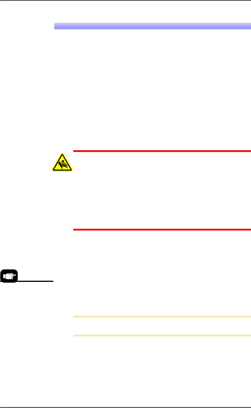
5. Set a torque wrench to 8.5 Nm (75 lbf-in.) and attach it to the
Belt Tension Tool (PN 952-0508-001 or higher).
Maintenance ■ Workspace, Head and Gantry
4—24 Data I/O • 096-0640-001B
back
Figure 4-13: A— The Gantry Belt Tensioning tool.
B—The tool in position. (Torque wrench not included.) In this orien-
tation, ignore the bubble-levels on the tool.
C—Plan view of the two posts parallel with the beam at the specified
torque.
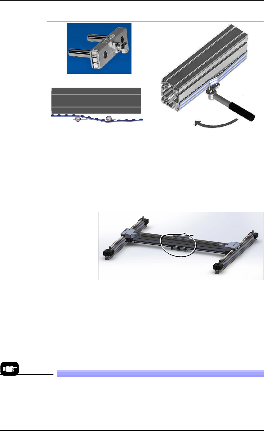
6. Attach the Belt Tension Tool as shown above near the greatest
expanse of belt such as at the center of the beam. (There is only
one gantry belt.)
Figure 4-14: Attach the tool to the greatest unsupported expanse of
belt.
7. Turn the wrench keeping the tool level. The two posts on the tool
should be in line (parallel with the beam) when the torque is
reached.
8. If the posts are not in line, contact Data I/O Customer Support or
a local Data I/O approved service representative.
Replacing a PNP Probe Assembly
Technicians trained on the PSV7000 can remove and re-install a Probe
Assembly if it is damaged or malfunctioning.
A
B
C
A spare Probe Assem-
bly comes with the
Self-Service Spares
Kit.