PSV7000_ Owners Manual_096-0460-001B - 第130页
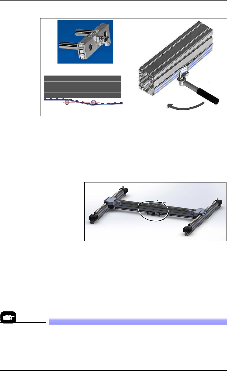
Maintenance ■ Workspace, Head and Gantry 4—24 Data I/O • 096-0640-001B back Figure 4-13: A — The Gantr y Belt T ensioning t ool. B —The tool in posi tion. (T orque wrench not included.) In this orien- tation, ignore the …
■ Workspace, Head and Gantry ◘ Gantry Belt Tension
PSV7000 Owner’s Manual 4—23
back
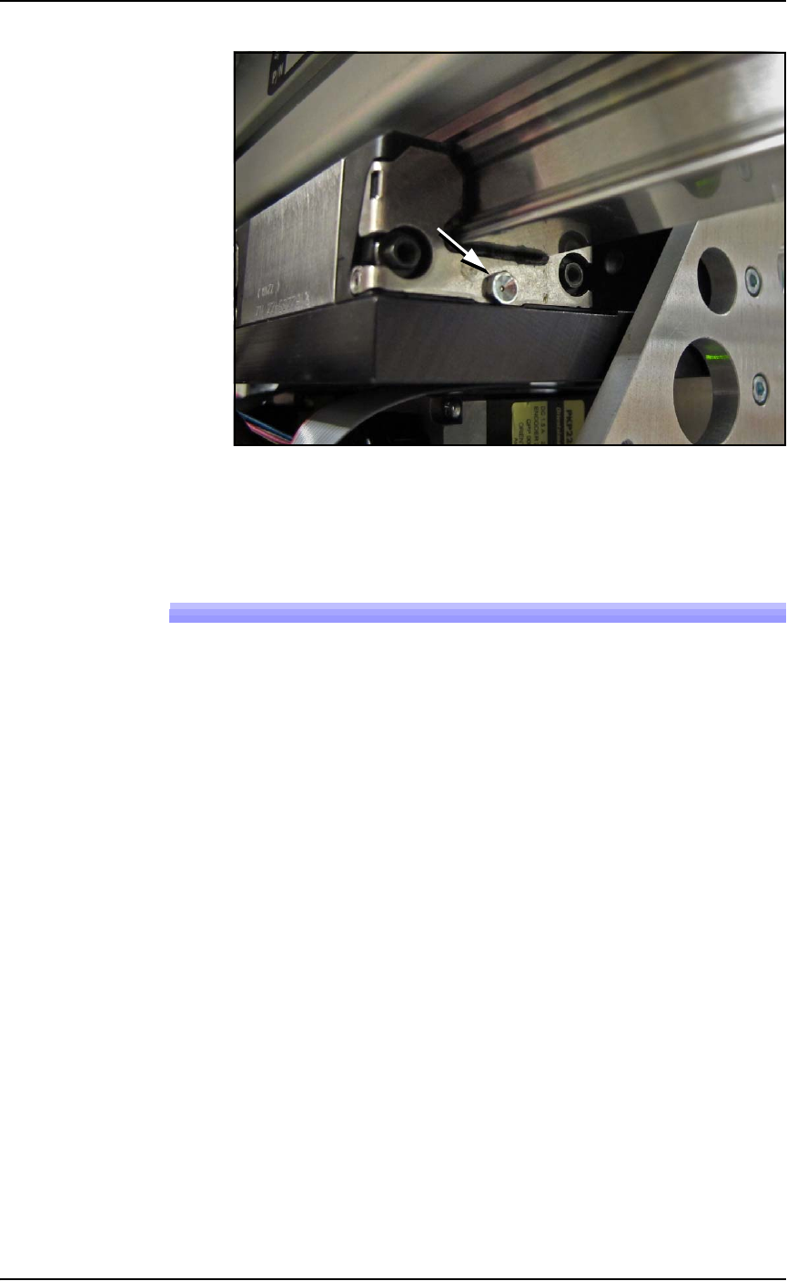
Figure 4-12: Grease fitting on the X-axis guide, shown.
5. Close the safety door.
Gantry Belt Tension
The Gantry drive belt may need tension adjusted depending on use.
If you hear the belt slapping or experience any anomalies, check the
tension as follows.
Requirements
• PSV7000 SELF-SERVICE SPARES KIT (PN 952-0507-001 or
higher)
• Torque wrench capable of 8.5 Nm (75 lbf-in.)
• The PSV7000 must be level
To check the belt tension:
1. Stop a job if one is running.
2. Click the Tool label to move the gantry to an accessible position.
3. Properly turn OFF the PSV7000 sub-systems and machine
power. See Shutting Down the PSV7000 System on page 2-7.
4. Open the front or rear safety door.
5. Set a torque wrench to 8.5 Nm (75 lbf-in.) and attach it to the
Belt Tension Tool (PN 952-0508-001 or higher).
Maintenance ■ Workspace, Head and Gantry
4—24 Data I/O • 096-0640-001B
back
Figure 4-13: A— The Gantry Belt Tensioning tool.
B—The tool in position. (Torque wrench not included.) In this orien-
tation, ignore the bubble-levels on the tool.
C—Plan view of the two posts parallel with the beam at the specified
torque.
6. Attach the Belt Tension Tool as shown above near the greatest
expanse of belt such as at the center of the beam. (There is only
one gantry belt.)
Figure 4-14: Attach the tool to the greatest unsupported expanse of
belt.
7. Turn the wrench keeping the tool level. The two posts on the tool
should be in line (parallel with the beam) when the torque is
reached.
8. If the posts are not in line, contact Data I/O Customer Support or
a local Data I/O approved service representative.
Replacing a PNP Probe Assembly
Technicians trained on the PSV7000 can remove and re-install a Probe
Assembly if it is damaged or malfunctioning.
A
B
C
A spare Probe Assem-
bly comes with the
Self-Service Spares
Kit.
■ Workspace, Head and Gantry ◘ Replacing a PNP Probe Assembly
PSV7000 Owner’s Manual 4—25
back
Requirement
• Long metric hex key set (extended reach)
•Spare Probe Assembly
To remove a Probe Assembly
1. End a job and move the PNP head to the TOOL position (click
System > Gantry > Tool) to move it to an accessible position.
2. Properly shut down the PSV7000 System; refer to Shutting Down
the PSV7000 System on page 2-7.
CAUTION: Possible Machine Damage! The PNP head,
Device-position Sensor, and gantry can be damaged by pushing
or pulling it improperly.
• Make sure the AH700 Application is closed.
• Only push or pull the head by gripping the triangular bracket
on the left side of the head.
3. Remove the probe from the target Probe Assembly. See Installing
the Correct Probes in the PSV7000 Operator’s Manual.
4. Disconnect the appropriate air hose form the vacuum generator
on the right side of the PNP head.
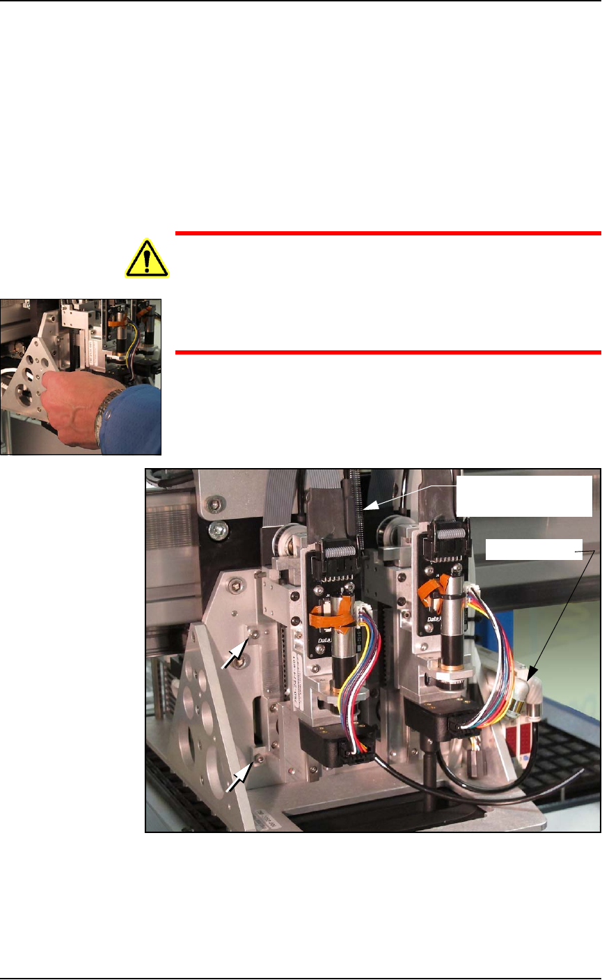
Figure 4-15: Probe Assembly #1 (on left) has air hose disconnected
and the Z-axis retention spring removed. Two of the four fasteners are
shown (arrows).
Air connector
Spring (on Probe #2)
(ref only)