PSV7000_ Owners Manual_096-0460-001B - 第133页
■ Workspace, Head and Gantry ◘ Replacing a PNP Probe Assembly PSV7000 Owner’s Manual 4—27 back Figure 4-1 7 : The PNP head with Pr obe Assembly #1 remove d. The slot for the ribbon cable and the two locating pins (arro w…
Maintenance ■ Workspace, Head and Gantry
4—26 Data I/O • 096-0640-001B
back
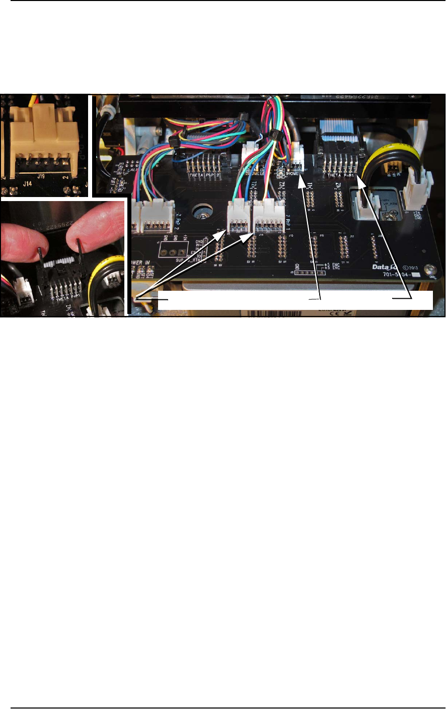
5. Disconnect the four electrical connectors from the Control Board
on the back of the PNP head.
For the 1Home and two Z connectors: push the thumb-tab up to
disconnect the latch.
For the Theta PNP 1: lift the two arms up as shown below.
Figure 4-16: Four Probe Assembly connectors. Detail of THETA PNP1 is
at ‘B.’ All others are style ‘A.’
6. Disconnect and remove the Z-axis retention spring.
7. Remove the four fasteners that hold the Probe Assembly to the
PNP head. Refer to Figure 4-15. (A long 2.5 mm hex key is
required.)
8. Carefully pull the Probe Assembly and air tubing toward the
front of the machine while guiding the cables on the back side
through the small opening.
Reinstalling the Probe Assembly
Generally, the reinstallation is in the reverse order of removal with
these precautions:
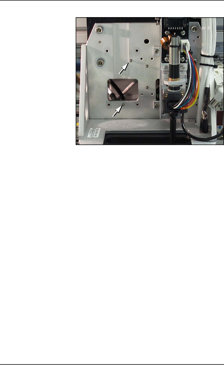
• Ensure the ribbon cable fits into the slot on the head bracket and
does not get pinched.
• Make sure the Probe Assembly mates up to the two locating pins
on the head bracket. See figure below.
Z PNP 1 connectors 1HOME THETA PNP1
A
B
B
■ Workspace, Head and Gantry ◘ Replacing a PNP Probe Assembly
PSV7000 Owner’s Manual 4—27
back
Figure 4-17: The PNP head with Probe Assembly #1 removed. The slot
for the ribbon cable and the two locating pins (arrows) are visible.
• Make sure that the probe set screw lines up with the flat on the
nub, and that the probe gets pushed up all the way past the
o-ring to the base of the head assembly.
• Make sure tubes and wires are securely stowed and fixed to
avoid being rubbed by any moving part. Slide the Z-axis move-
ment up and down by hand to verify clearance.
Maintenance ■ Programmers
4—28 Data I/O • 096-0640-001B
back
Programmers
FlashCORE Programmer Diagnostics
To optimize programming yields, voltages within the FlashCORE
programmer need to be calibrated once each year. This is a more
thorough HW test than the 'POST' (Power-On-Self-Test) as well as
ensuring that each programmer's precision reference is still within its
specified operating range.
Annual programmer Compliance Verification (CV) can be performed
by Data I/O at customer sites. This on-site visit is included if you have
an APS (Annual Programmer Support) contract (customer pays
travel costs).
Optionally, customer can purchase a Diagnostic Adaptor Board
(DAB) and perform the compliance diagnostics themselves. Contact
sales to purchase a DAB.
Tools required
• Diagnostic Adapter Board (DAB), Data I/O part number
910-2200-003 (or higher).
This Diagnostic Adapter Board detects problems related to
FlashCORE (FC) programmer hardware failure. The DAB tests the
Waveform Circuit Board and Backplane Circuit Board. The DAB can
also be used to locate problems that have not yet shown symptoms.
The DAB performs these nine tests:
Running the Programmer Diagnostic Test
To run diagnostic tests on FlashCORE programmer(s):
1. Finish a job if one is running; wait for the PNP head to park.
2. Turn OFF the programmer circuit breaker at the Power Panel
(down position).
• Bus Test
•
Vpp Overcurrent Test
• Adapter ID Test • I2C Bus Test
• LED Driver Test
• DAC Calibration Test
•
G Node Test • Gslew Test
• Vcc Overcurrent Test