PSV7000_ Owners Manual_096-0460-001B - 第136页
Maintenance ■ Programmers 4—30 Data I/O • 096-0640-001B back Sample dialog.txt file: Diagnostic Pass #1 Run Vpp Overcurrent test. DUT 1 G1 Vpp overcurrent is sensed at 57 mA. DUT 1 G2 Vpp overcurrent is sensed at 57 mA. …
■ Programmers ◘ FlashCORE Programmer Diagnostics
PSV7000 Owner’s Manual 4—29
back
3. Exit AH700 to return to TaskLink.
WARNING: ESD hazard! To prevent ESD shock, before you
touch the Socket Adapter, discharge static electricity from
yourself by touching a common ground or an unpainted
metal surface.
When at the PSV7000 Machine, always wear a wrist strap
containing a 1 M-ohm min. to 10 M-ohm max. current limit-
ing resistor. Connect the antistatic wrist strap to the ground-
ing socket on the front or back of the PSV7000 Machine.
WARNING: Possible collision hazard! The high speed and
force of the gantry can seriously harm anyone working inside
the workspace.
When working within the machine workspace, moving the
PNP head must be the responsibility of only one qualified
individual. All others must stay clear of the machine controls
to prevent injury to that person.
Ensure that a job is Paused or Finished, or the system power
is OFF prior to opening any safety doors.
4. Remove the Socket Adapter from the target programmer and
insert the Diagnostic Adapter Board, ensuring that it aligns cor-
rectly on the adapter pins. Screw down the two bracket screws
(4 mm hex key).
5. Turn the programmer circuit breaker at the Power Panel ON (up
position).
6. Start TaskLink and click Tools > Run Programmer Diagnostics.
7. On the Diagnostics window, select the programmer with the
DAB installed.
8. Click Test All.
The pass/fail test results are displayed in TaskLink and are also
written to
/fdrroot/system/diaglog.txt
(and to the CF-card of the
target FlashCORE programmer). These files can be viewed in
TaskLink and saved (on the Handler Computer).
If any of the tests show Fail in the TaskLink display, contact your
nearest Data I/O Service Center for repair options. To help our service
personnel diagnose the problem, please e-mail both the
eventlog.txt
and
diaglog.txt
files.
The wrist strap
Data I/O PN is
440-0021-001.

Maintenance ■ Programmers
4—30 Data I/O • 096-0640-001B
back
Sample
dialog.txt
file:
Diagnostic Pass #1
Run Vpp Overcurrent test.
DUT 1 G1 Vpp overcurrent is sensed at 57 mA.
DUT 1 G2 Vpp overcurrent is sensed at 57 mA.
DUT 1 G3 Vpp overcurrent is sensed at 57 mA.
DUT 1 G4 Vpp overcurrent is sensed at 57 mA.
DUT 2 G1 Vpp overcurrent is sensed at 57 mA.
DUT 2 G2 Vpp overcurrent is sensed at 57 mA.
DUT 2 G3 Vpp overcurrent is sensed at 57 mA.
DUT 2 G4 Vpp overcurrent is sensed at 57 mA.
Error: DUT 3 G1 Vpp overcurrent is not sensed from 50
mA to 70 mA.
Error: DUT 3 G2 Vpp overcurrent is not sensed from 50
mA to 70 mA.
Error: DUT 3 G3 Vpp overcurrent is not sensed from 50
mA to 70 mA.
Error: DUT 3 G4 Vpp overcurrent is not sensed from 50
mA to 70 mA.
DUT 4 G1 Vpp overcurrent is sensed at 57 mA.
DUT 4 G2 Vpp overcurrent is sensed at 57 mA.
DUT 4 G3 Vpp overcurrent is sensed at 57 mA.
DUT 4 G4 Vpp overcurrent is sensed at 57 mA.
Diagnostics failed.
Replacing a FlashCORE Programmer
If a programmer is not working properly, it can be removed and
replaced with another one.
Tools Required
• Cable Tie tool
• Clippers to cut cable tie
• 3 mm hex key (Allen wrench)
• Access door key that came with your PSV7000
WARNING: Electric shock hazard! Injury or death may result
from contact to parts inside the machine. Shut off the
PSV7000 System by turning OFF the main power switch
before working on or near the gantry, before opening any
access doors or removing any cabinet panels.
■ Programmers ◘ Replacing a FlashCORE Programmer
PSV7000 Owner’s Manual 4—31
back
To remove a FlashCORE programmer:
1. Properly turn OFF the PSV7000 sub-systems and machine
power. See Shutting Down the PSV7000 System on page 2-7.
2. With the supplied door key, open the lower, right front access
door.
3. Locate the target programmer and follow the heavy gray power
cable to the connection panel on the right side of the machine.
Refer to Figure 4-18 on page 4–31.
4. Mark the cable (to re-install in the same place) and pull the con-
nector straight out.
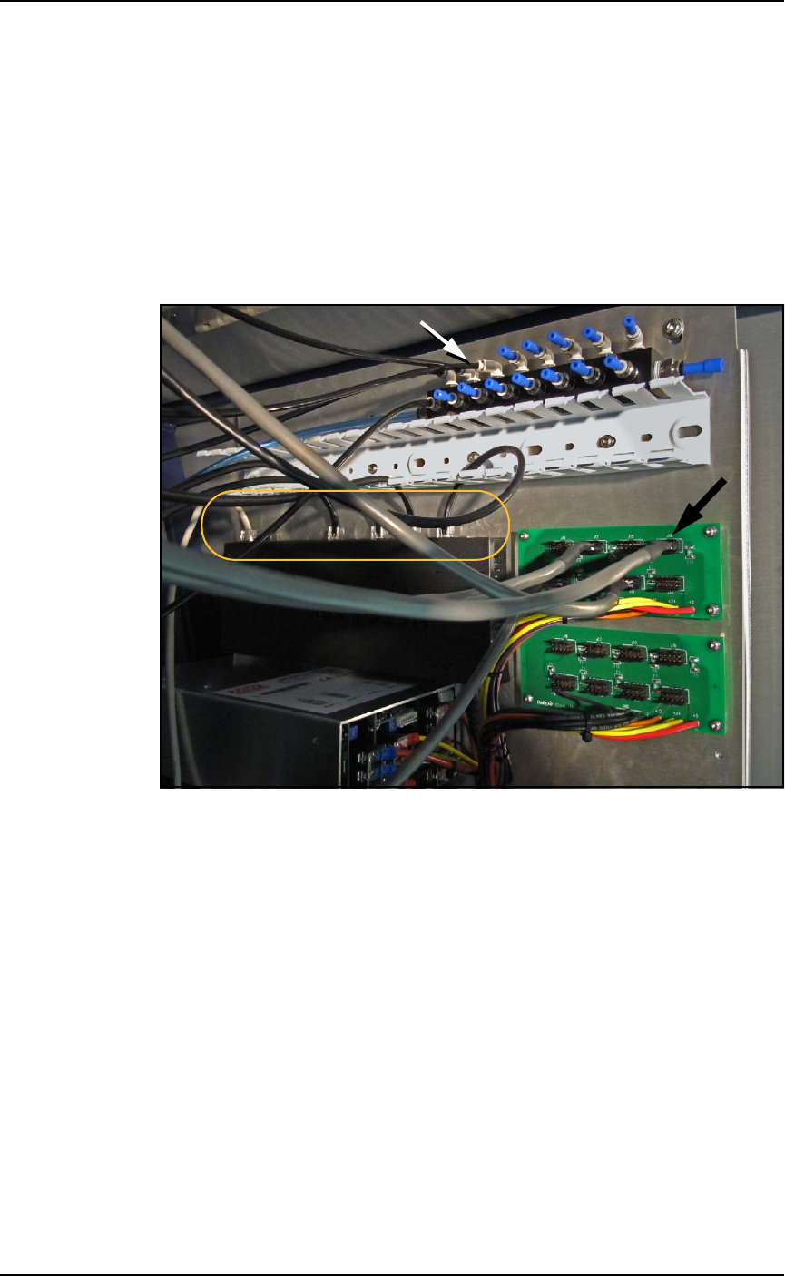
Figure 4-18: The right side connection panel inside the right front
access door. Power cables (black arrow), Pneumatic tubing (white
arrow), and the Ethernet connections (circled).
5. Follow and mark the thin black tubing to the air manifold on the
right mounting plate.
6. Disconnect the air tube at the one-touch connector (push in on
the collar while pulling the tube out).