PSV7000_ Owners Manual_096-0460-001B - 第150页
Maintenance ■ Troubleshoot ing 4—44 Data I/O • 096-0640-001B back Troubleshooting This section contains solutions to problems that may arise during operation of the PSV7000. T roubleshooting for the T ape Output System i…
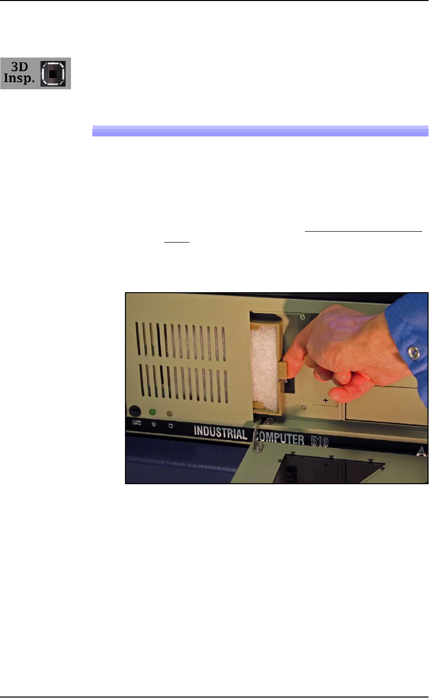
■ 3D Coplanarity Inspection System ◘ Cleaning the 3D Inspection PC Filter
PSV7000 Owner’s Manual 4—43
back
3D Coplanarity Inspection System
The 3D Inspection System requires little maintenance. The 3D Inspec-
tion PC is just below the Handler PC on the left side of the machine.
Cleaning the 3D Inspection PC Filter
1. Shut down the 3D Inspection PC using the Windows Start menu
as follows:
1a. Use the Scroll Lock key on the keyboard to switch to the 3D
Inspection PC. (Scroll-Lock > Scroll-Lock > 3.)
1b. Exit the UltraVim Application software. Then at the dialog,
type EX to exit.
1c. Shut down the 3D Coplanar PC with the Windows START
menu.
2. Open the PC door with the key.
3. Pull the small tab on the filter tray toward you and slide to the
right.
4. Inspect the filter. It should be white. Clean or replace with a new
filter.
5. Replace the filter tray and close and lock the PC door.
To turn

Maintenance ■ Troubleshooting
4—44 Data I/O • 096-0640-001B
back
Troubleshooting
This section contains solutions to problems that may arise during
operation of the PSV7000.
Troubleshooting for the Tape Output System is covered in a separate
heading; see Troubleshooting the Tape Output System on page 4-57.
Also, see PSV7000 on-screen Help for a more detailed Trouble-
shooting chart.
Headings below cover:
• Common Error Messages
• Collect all PSV7000 System Logs on page 4-45
• Programming Problems on page 4-48
• Pick and Place Problems on page 4-49
• Air Pressure Problems on page 4-50
• Tube Input and Output Problems on page 4-51
• Tray Feeder Problems on page 4-52
• Handler Computer Failure on page 4-52
• Laser Marking Problems on page 4-53
Common Error Messages
Lamp color Error Messages Possible Resolution
Red
“Cannot con-
nect to the motion
controller.”
• Check that both Emergency Stop buttons are OFF.
• Check that all safety doors are closed.
• Properly shut down the PSV7000 Machine if possible, and
restart the system.
Red
“E-STOP
ACTIVATED” but
the OK button is
grayed out (unavail-
able)
• Check that both E-Stop buttons are released.
• Check that all safety doors are closed.
• If a restart is necessary, press Ctrl + Alt + Del on the keyboard

■ Troubleshooting ◘ Collect all PSV7000 System Logs
PSV7000 Owner’s Manual 4—45
back
Restarting after Trouble
If the AH700 Software closes, locks up, or experiences some trouble
that qualifies as a crash, then the PSV7000 Machine power must be
turned OFF for 20 seconds prior to restarting the software.
Collect all PSV7000 System Logs
Collect PS Logs is a software utility on AH700 Software that collects all
log files from PSV7000. It creates a ZIP file containing all the infor-
mation that Data I/O or trained service technicians need to evaluate
your PSV7000 Machine status.
Yellow
TRAY NOT
PRESENT
Conditions: You swapped the input tray but PSV7000 does not
detect the tray and when you click Run, you get error message
Tray Not Present; or the Run window shows a tray where there is
none.
• Re-install the tray.
• At the Run window, the Tray Present Sensor should be ON.
• If the tray is still not detected, remove the tray and place a finger
over tray present sensor.
–If sensor is working, tray outline appears. Re-install tray.
–If sensor is not working, the tray outline does not appear—con-
tact
Data I/O Customer Support or a local Data I/O approved
service representative.
Red
Z MOTION
ERROR 800: LIMIT
EXCEEDED ON
AXIS 2
Conditions: A Red ERROR box appears in bottom right corner of
the Monitor.
Contact Data I/O Customer Support or a local Data I/O approved
service representative.
Red/Yellow
ERROR: TAPE
OUT
• If a device is jammed in the Tape Output System, clear it.
Acknowledge the error message by pressing the ESC key. Then
click
OK on the PSV7000 Monitor.
• If above doesn't work, call the Service Technician.
Red
MAIN AIR OFF
• Check that the main input air valve is in the ON position.
• Check that the main air hose is connected.
• Check that the air pressure is within the required range (green
LED readout instead of red.)
• Contact Data I/O Customer Support or a local Data I/O
approved service representative.
Red
VACUUM
ERROR
• See Adjusting the Vacuum Generator Sensors on page 4-17.
• Contact Data I/O Customer Support or a local Data I/O
approved service representative.
Lamp color Error Messages Possible Resolution