PSV7000_ Owners Manual_096-0460-001B - 第156页
Maintenance ■ Troubleshoot ing 4—50 Data I/O • 096-0640-001B back Air Pressure Problems Lamp Color Air Pressure T rouble Possible R esolutions Red There is no main air pressure. Make sure that the main air switch o…

■ Troubleshooting ◘ Pick and Place Problems
PSV7000 Owner’s Manual 4—49
back
Pick and Place Problems
Lamp
Color
Pick and Place Trouble Possible Resolutions
Red/
Yellow
Devices are not being
placed into sockets or output
media accurately.
The PNP head does not
center on the devices.
Check that the probe is not bent.
Check all fasteners and connections on the
head and gantry. Also see Inspecting Gantry
Parts on page 4-22.
Clean the Device-position Sensor. See Cleaning
the Device Position Sensor on page 4-12.
Adjust the X-, Y-, and Z-axis positions using
the adjustment arrows on the Gantry window.
For more information, see Teaching the Work-
space Locations on page 3-9.
Yellow/
Red
One of the probes expe-
riences pick and/or place
errors regularly while the
other does not.
Contact Data I/O Customer Support or a local
Data I/O approved service representative.
The Probe is dropping
devices.
Clean or replace the Probe Tips. See Pick and
Place Probes on page 4-14.
Clean the vacuum filters. See Vacuum Generator
Filters on page 4-19.
Check the main input air pressure; refer to
Connecting Air on page 2-3.
A probe attempts to
pick a device twice even
though it picked up the
device the first time.
The Vacuum sensor may need calibrating. See
To Adjust Probe Vacuum Generator Sensors: on
page 4-17.
If programming TQFP 144, you can increase
the value for ‘suckup time’ in the Package File
to maximum value of 500 ms. See the Setup
window > System > Package File. Refer to the
on-screen Help.
Devices are bouncing.
The socket air pressure may be too high.
Reduce the socket actuation air pressure. See
Adjusting the Socket Actuator Air Pressure on the
Programmers on page 4-9
Red/
Yellow
Pick or place errors at
all programmers.
The socket is not opening completely—the air pres-
sure might be set too low.
Adjusting the Vacuum Generator Sensors on page
4-17.
Increase the socket actuation air pressure. See
Adjusting the Socket Actuator Air Pressure on the
Programmers on page 4-9

Maintenance ■ Troubleshooting
4—50 Data I/O • 096-0640-001B
back
Air Pressure Problems
Lamp
Color
Air Pressure Trouble Possible Resolutions
Red
There is no main air
pressure.
Make sure that the main air switch on the
Power Panel is in the ON position.
Check that the air regulator on the Power
Panel displays within the acceptable range:
PSV7000 Specifications on page 1-9.
If not:
• Check your shop air pressure.
• Shut down and replace the filter. See Replac-
ing the Input Air Filter on page 4-18.
The digital display on the regulator will be
green when air pressure is within the correct
range and red when it is out of range. The reg-
ulator has been set at the factory and is not
adjustable.
Red
There is no (or low)
vacuum on the PNP probes.
Check that the probes are not loose and that
the o-rings are not destroyed or leaking.
See Pick and Place Probes on page 4-14.
Determine if the PNP head probes are clogged.
Clean if necessary. Refer to Removing and
Installing a Probe in the PSV7000 Operator’s
Manual.
Check the probe vacuum and Blow-off sole-
noids; Adjusting the Vacuum Generator Sensors
on page 4-17.
Clean the vacuum generator filters and silenc-
ers; Vacuum Generator Filters and Silencers on
page 4-19
■ Troubleshooting ◘ Tube Input and Output Problems
PSV7000 Owner’s Manual 4—51
back
Tube Input and Output Problems
This information is subject to change.
Lamp
Color
Vibrator Tube Trouble Possible Resolutions
Neither of the tube
platforms vibrates.
Make sure that tube input or tube output has
been selected on the Setup window.
Check that the power switch at each Tube
Module is ON.
Make sure the vibration and frequency con-
trols are set properly.
Only one tube plat-
form vibrates.
Check that the power switch at each Tube
Module is ON.
Check the power cable source connection.
Check the fuse on the input module.
PSV7000 is putting the
wrong number of devices
into the output tubes.
Reset devices per tube in the Gantry window
as follows:
1. At the Setup window, Options tab, ensure that
Input and/or Output options are set to tubes.
2. Click System > Gantry (you may be prompted
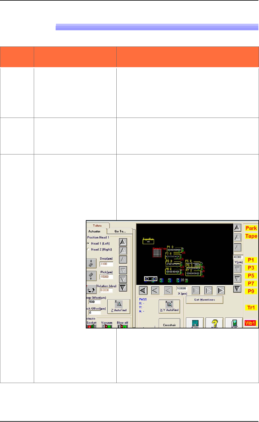
to enter your password). Click the yellow Vib1
label to move the PNP head to the first posi-
tion of the input vibrator.
Figure 4-27: The Vib1 label has been clicked.
3. Click the Tubes tab, then enter the correct
number of devices per tube in the Chips/Tube
field.
4. Click Save to store the new settings to the
Package File.