PSV7000_ Owners Manual_096-0460-001B - 第159页
■ Troubleshooting ◘ Laser Marking Problems PSV7000 Owner’s Manual 4—53 back Figure 4-29: The RAID solid state hard drives. The Handler PC cover has been removed. Laser Marking Problems Lamp color Tr o u b l e Possible R …
Maintenance ■ Troubleshooting
4—52 Data I/O • 096-0640-001B
back
Tray Feeder Problems
Handler Computer Failure
A Handler computer drive fails. A message or behavior indicates that
a computer has crashed.
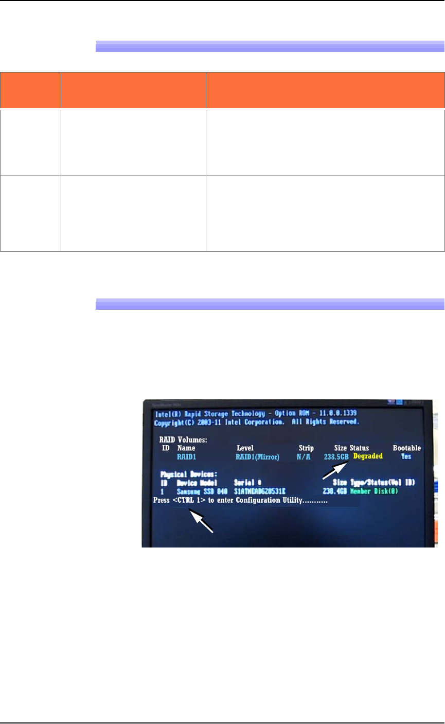
Your PSV7000 System is equipped with a mirror-backup system
called RAID that creates a real-time ghost image. You will see an error
message display very quickly at system start-up.
Figure 4-28: This message, DEGRADED, will display for about seven
seconds at startup if a Handler drive has failed.
Your PSV7000 System will continue to operate as normal on the
backup drive. However, the failed drive must be replaced for con-
tinued safety. After the failed drive is identified and replaced, the
message on-screen will read REBUILDING. After it has rebuilt, the
next time you start up it will read NORMAL.
Contact Data I/O Support or your nearest Data I/O representative.
Lamp
Color
Tray Feeder Trouble Possible Resolutions
Yellow
The Run window indi-
cates a tray is present on the
Data I/O Dual Tray Feeder
when there is no tray there,
or vice versa.
Navigate to the System > MISC I/O window
and verify that the Tray Present Sensor = ON.
Probes miss-pick or
misplace devices at the trays.
Probes hit devices in a
tray hard at one end and not
the other.
Check that the tray feeder is level. Adjust the
outside mounting bar if necessary.
■ Troubleshooting ◘ Laser Marking Problems
PSV7000 Owner’s Manual 4—53
back
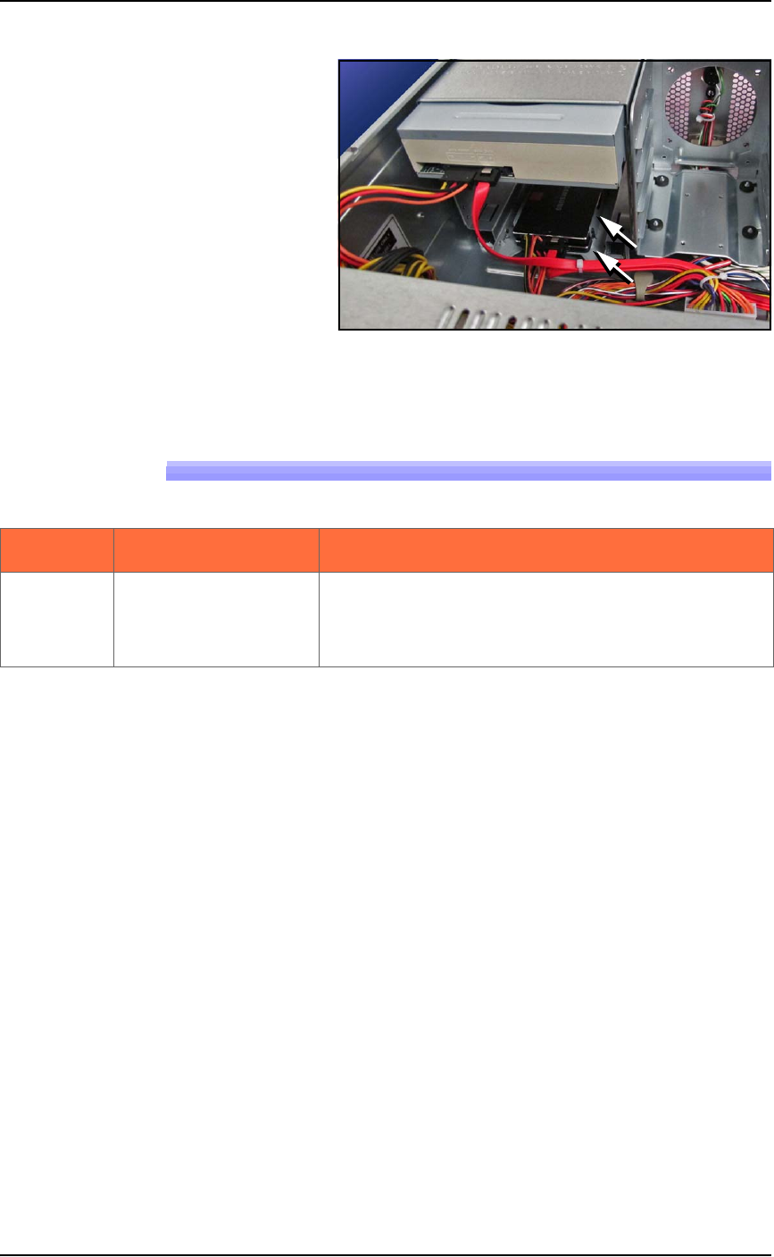
Figure 4-29: The RAID solid state hard drives. The Handler PC cover
has been removed.
Laser Marking Problems
Lamp color Trouble Possible Resolutions
The Fume
Extractor doesn’t start
when powered up
(power switch is ON).
Properly turn OFF the PSV7000 System. Open the
PSV7000 access door and check the fuse just below
the power switch on the filter enclosure. See Fig-
ure 4-21 on page 4–36.
Maintenance ■ Tape Output System
4—54 Data I/O • 096-0640-001B
back
Tape Output System
The Tape Output System is an optional system for placing and taping
programmed devices into device tape.
Items not covered here can be found in the TM-50 Taping Module
User’s Guide that came with your PSV7000 System.
Cleaning the Pressure Seal
The Pressure Seal Tape Output System requires cleaning to prevent
problems with breaking the device tape or tearing the tape sprocket
holes. Cleaning removes build up from the cover tape application
rollers and the drive sprocket top pressure idler wheel.
Cleaning Tools Required
• Dry or damp shop towel
• A reel of empty device tape (carrier tape)
• A reel of cover tape
To clean the Pressure Seal Tape Output System:
1. Turn ON the PSV7000 System power and air.
2. Start TaskLink.
3. Select a job that requires the use of the tape output.
4. Click Run (and Yes or OK to subsequent dialogs), which opens
AH700 automatically.
5. Click Start.
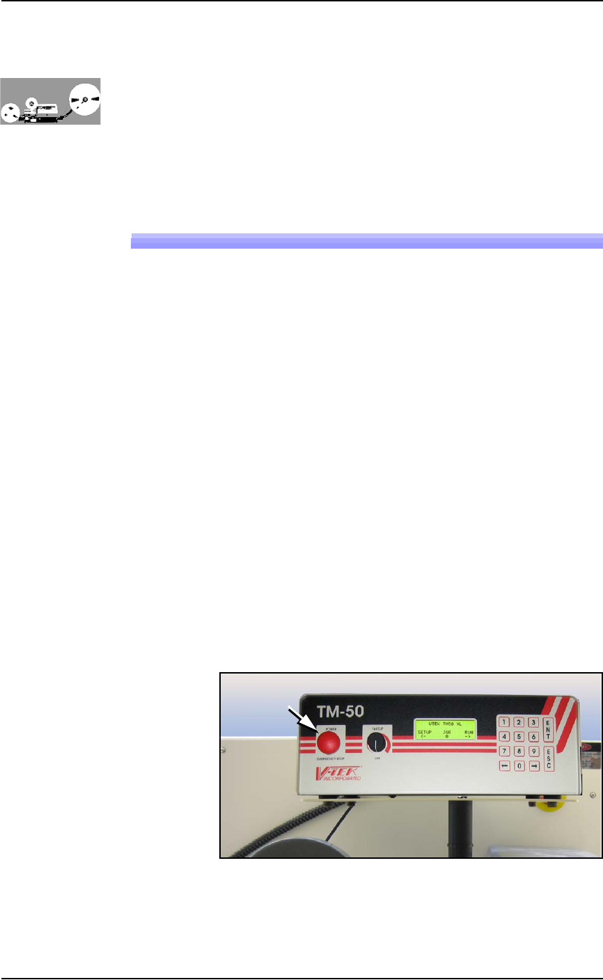
6. Turn on the Tape Output Controller by pushing the red Power
button. Refer to Figure 4-30.
7. At the V-TEK start-up screen, select Setup by pressing the left
arrow button.
Figure 4-30: Tape Output Module Controller. The arrow points to the
Power On/Off button which is also the Emergency-Stop (for the
Tape-Out Module only!).