PSV7000_ Owners Manual_096-0460-001B - 第160页
Maintenance ■ Tape Output System 4—54 Data I/O • 096-0640-001B back Tape Output System Th e T ap e Ou t p u t S y s te m i s a n op t i onal system for placing and taping programmed devices into device tape. Items not co…
■ Troubleshooting ◘ Laser Marking Problems
PSV7000 Owner’s Manual 4—53
back
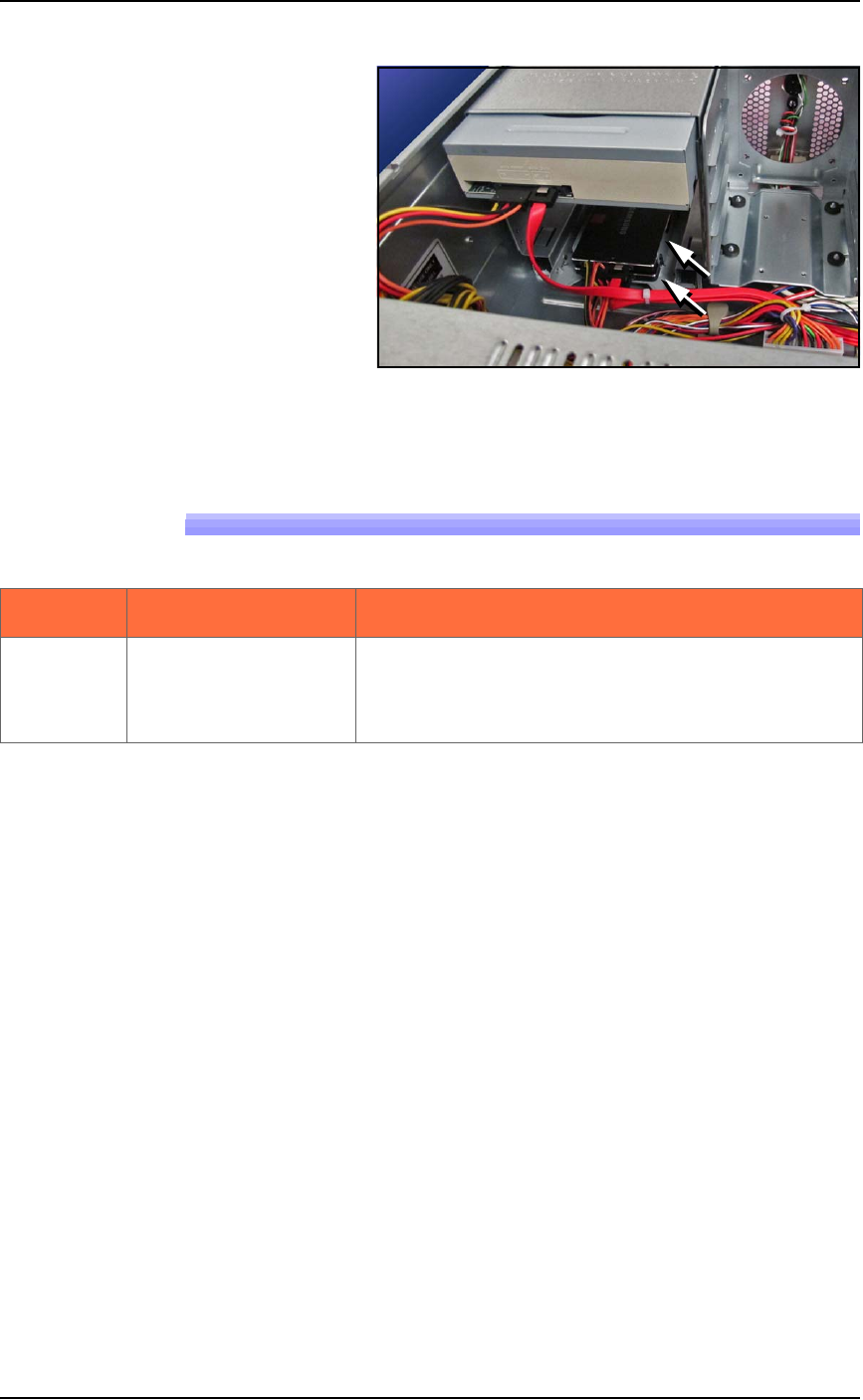
Figure 4-29: The RAID solid state hard drives. The Handler PC cover
has been removed.
Laser Marking Problems
Lamp color Trouble Possible Resolutions
The Fume
Extractor doesn’t start
when powered up
(power switch is ON).
Properly turn OFF the PSV7000 System. Open the
PSV7000 access door and check the fuse just below
the power switch on the filter enclosure. See Fig-
ure 4-21 on page 4–36.
Maintenance ■ Tape Output System
4—54 Data I/O • 096-0640-001B
back
Tape Output System
The Tape Output System is an optional system for placing and taping
programmed devices into device tape.
Items not covered here can be found in the TM-50 Taping Module
User’s Guide that came with your PSV7000 System.
Cleaning the Pressure Seal
The Pressure Seal Tape Output System requires cleaning to prevent
problems with breaking the device tape or tearing the tape sprocket
holes. Cleaning removes build up from the cover tape application
rollers and the drive sprocket top pressure idler wheel.
Cleaning Tools Required
• Dry or damp shop towel
• A reel of empty device tape (carrier tape)
• A reel of cover tape
To clean the Pressure Seal Tape Output System:
1. Turn ON the PSV7000 System power and air.
2. Start TaskLink.
3. Select a job that requires the use of the tape output.
4. Click Run (and Yes or OK to subsequent dialogs), which opens
AH700 automatically.
5. Click Start.
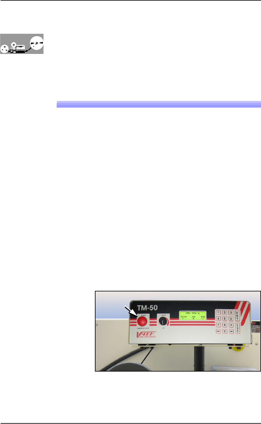
6. Turn on the Tape Output Controller by pushing the red Power
button. Refer to Figure 4-30.
7. At the V-TEK start-up screen, select Setup by pressing the left
arrow button.
Figure 4-30: Tape Output Module Controller. The arrow points to the
Power On/Off button which is also the Emergency-Stop (for the
Tape-Out Module only!).

■ Tape Output System ◘ Cleaning the Pressure Seal
PSV7000 Owner’s Manual 4—55
back
8. Configure the Tape Output Controller by setting the following:
At the Setup menu:
• reset Count Stop to desired amount:
Press 1, to re-zero the present count
Press 2, then enter the desired number, then press the ENT
button.
• select the desired device tape pitch from the Pitch Selection
menu. Then press ENT.
Note: The pitch can be determined by using the pitch setting decal
located on the loading track or the pitch setting guide found at the
front of the TM-50 Taping Module User’s Guide.
At the Advance menu:
• set the number of pockets to advance to 1. Then press ENT.
At the Speed menu:
• set the advance speed between 40 to 100 depending on the
device tape width and device size. Then press ENT.
Note: Prevent device tape breakage and advancement problems
with small devices and narrower tape widths by setting slower
speeds— in the range 40 to 60.
Higher speeds may cause the devices to be dislodged from the pock-
ets or may cause the sprocket holes on the tape to rip out.
At the Jog menu
• jog the device tape forward to align the pocket with the
PNP head.
At the Mode menu
• select PSA mode for pressure seal cover tape. An asterisk indi-
cates the current setting. Then press ESC.
Note: The Heat Seal switch should be OFF.
At the Run menu
•select Run Mode. The run window displays all the selected
setup parameters.
• verify all settings for accuracy.
9. Inspect the PSA seal rollers for build up of grime from the cover
tape. See Figure 4-31.
For more information,
see the TM-50 Taping
Module Users Guide
that came with your
equipment.