PSV7000_ Owners Manual_096-0460-001B - 第162页
Maintenance ■ Tape Output System 4—56 Data I/O • 096-0640-001B back Figure 4-3 1: On the T ape Out Module, the PSA Seal Rollers (arrows) and Sprocket Idler with O-rings. CAUTION: Possible Machine Damage! Do not use solve…

■ Tape Output System ◘ Cleaning the Pressure Seal
PSV7000 Owner’s Manual 4—55
back
8. Configure the Tape Output Controller by setting the following:
At the Setup menu:
• reset Count Stop to desired amount:
Press 1, to re-zero the present count
Press 2, then enter the desired number, then press the ENT
button.
• select the desired device tape pitch from the Pitch Selection
menu. Then press ENT.
Note: The pitch can be determined by using the pitch setting decal
located on the loading track or the pitch setting guide found at the
front of the TM-50 Taping Module User’s Guide.
At the Advance menu:
• set the number of pockets to advance to 1. Then press ENT.
At the Speed menu:
• set the advance speed between 40 to 100 depending on the
device tape width and device size. Then press ENT.
Note: Prevent device tape breakage and advancement problems
with small devices and narrower tape widths by setting slower
speeds— in the range 40 to 60.
Higher speeds may cause the devices to be dislodged from the pock-
ets or may cause the sprocket holes on the tape to rip out.
At the Jog menu
• jog the device tape forward to align the pocket with the
PNP head.
At the Mode menu
• select PSA mode for pressure seal cover tape. An asterisk indi-
cates the current setting. Then press ESC.
Note: The Heat Seal switch should be OFF.
At the Run menu
•select Run Mode. The run window displays all the selected
setup parameters.
• verify all settings for accuracy.
9. Inspect the PSA seal rollers for build up of grime from the cover
tape. See Figure 4-31.
For more information,
see the TM-50 Taping
Module Users Guide
that came with your
equipment.
Maintenance ■ Tape Output System
4—56 Data I/O • 096-0640-001B
back
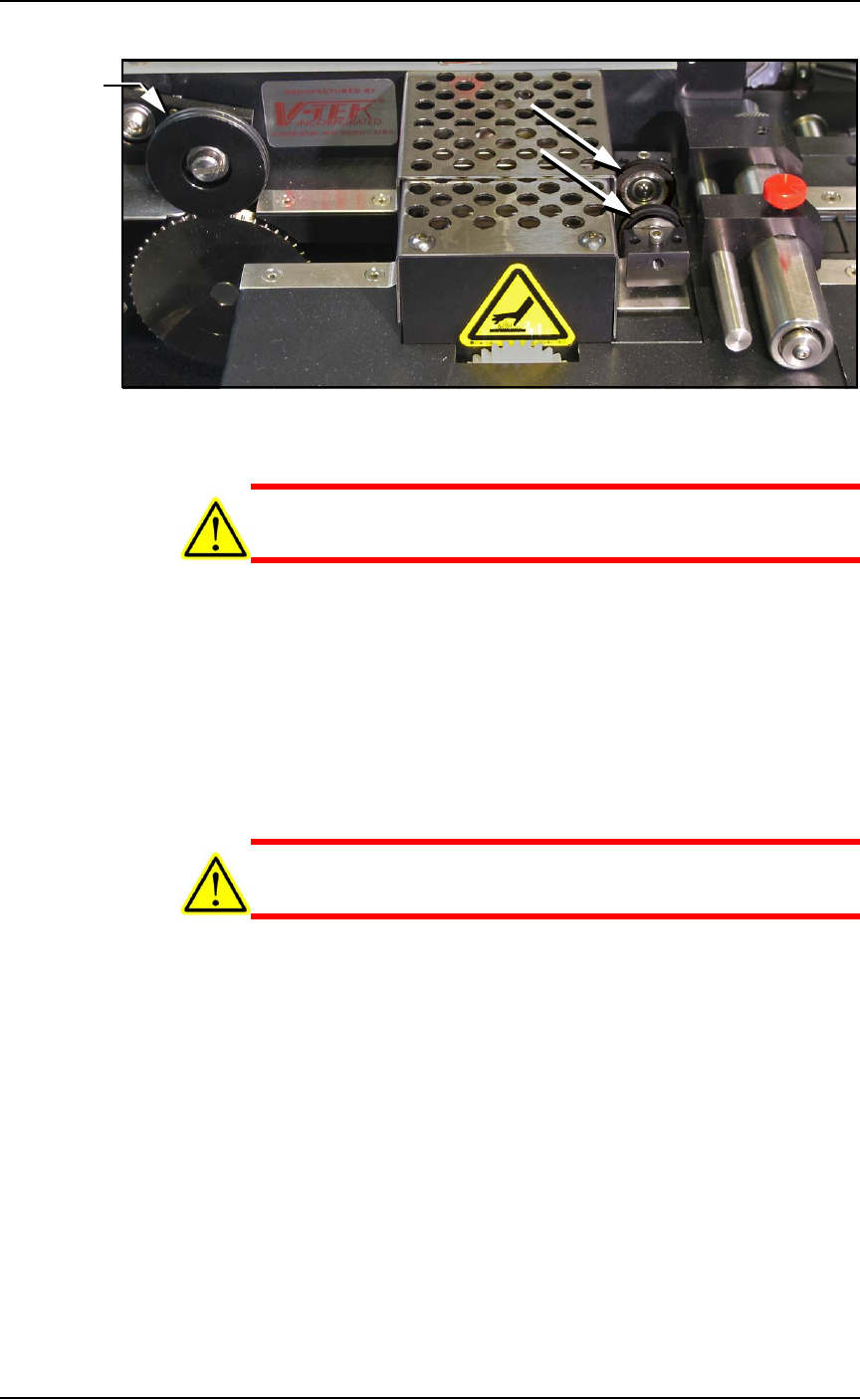
Figure 4-31: On the Tape Out Module, the PSA Seal Rollers (arrows)
and Sprocket Idler with O-rings.
CAUTION: Possible Machine Damage! Do not use solvents other
than alcohol when cleaning the black polyurethane wheels.
10. If grime buildup exists on the PSA Seal rollers—
10a.Using a shop towel and alcohol or alcohol wipes, clean the
build up from the cover tape application rollers. Hold the
alcohol cloth on the roller and rotate the roller 360°.
10b.Repeat procedure for the other application roller.
11. Inspect the drive sprocket top idler and rubber O-rings for any
build up from the cover tape. See Figure 4-31.
12. If grime buildup exists on the idler and O-rings—
CAUTION: O-rings might be easily damaged. Handle gently to
avoid breaking them.
12a.Gently remove the two O-rings from the drive sprocket
idler.
12b.Using a shop cloth and alcohol or a commercial alcohol
wipe, remove all grime from O-rings.
12c.Wipe the idler clean.
12d.Reinstall the dry O-rings onto the idler.
O-rings

■ Tape Output System ◘ Adjusting Pressure of the PSA Seal Rollers
PSV7000 Owner’s Manual 4—57
back
Adjusting Pressure of the PSA Seal
Rollers
1. Advance the device tape with the cover tape through the Seal
Rollers using the manual advance pedal. Advance enough pock-
ets to correctly align the cover tape on the carrier tape.
2. Perform a peel back test by peeling the cover tape from the carrier
tape. Notice how well the cover tape adheres to the device tape.
Perform a twist test by giving the tape a slight twist. Notice if the
cover tape detaches from the device tape.
If either test produces loose cover tape, increase the application
roller pressure by screwing the PSA Seal pressure adjustment
screw in (clockwise).
If both tests look acceptable, visually inspect the sealed device
tape for adhesive that may have been squeezed out during
application. If adhesive is visible, the Seal Roller pressure is too
high. Decrease the application roller pressure by screwing the
PSA Seal pressure adjustment screw out and retest.
Troubleshooting the Tape Output
System
The Tape Output System contains sensors that detect these fault con-
ditions:
• a device is on top the device tape (carrier tape)—Track Jam Sen-
sor
• no cover tape is on the reel—Cover Tape Sensor
• device tape is not properly inserted in the device tape track—
Device Tape Present Sensor
• a pocket in the carrier tape is empty—Pocket Empty Sensor
When the AH700 software displays the error message Tape Out Unit,
one of the tape output system sensors has been triggered. The most
likely sensors to trigger are the Device Jam and Device Tape sensors.
See Figure 4-32 on page 4-58.