PSV7000_ Owners Manual_096-0460-001B - 第164页
Maintenance ■ Tape Output System 4—58 Data I/O • 096-0640-001B back Figure 4-32: Optical Fiber Amplif iers. Cover T ape Present and Empty Pocke t, respectively . Amplifier doors are open in the right side view . Fr o n t…

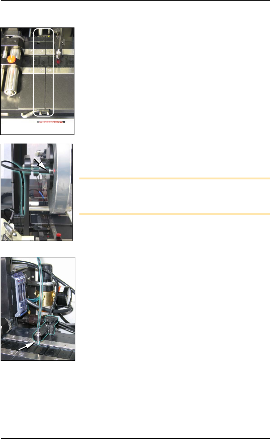
■ Tape Output System ◘ Adjusting Pressure of the PSA Seal Rollers
PSV7000 Owner’s Manual 4—57
back
Adjusting Pressure of the PSA Seal
Rollers
1. Advance the device tape with the cover tape through the Seal
Rollers using the manual advance pedal. Advance enough pock-
ets to correctly align the cover tape on the carrier tape.
2. Perform a peel back test by peeling the cover tape from the carrier
tape. Notice how well the cover tape adheres to the device tape.
Perform a twist test by giving the tape a slight twist. Notice if the
cover tape detaches from the device tape.
If either test produces loose cover tape, increase the application
roller pressure by screwing the PSA Seal pressure adjustment
screw in (clockwise).
If both tests look acceptable, visually inspect the sealed device
tape for adhesive that may have been squeezed out during
application. If adhesive is visible, the Seal Roller pressure is too
high. Decrease the application roller pressure by screwing the
PSA Seal pressure adjustment screw out and retest.
Troubleshooting the Tape Output
System
The Tape Output System contains sensors that detect these fault con-
ditions:
• a device is on top the device tape (carrier tape)—Track Jam Sen-
sor
• no cover tape is on the reel—Cover Tape Sensor
• device tape is not properly inserted in the device tape track—
Device Tape Present Sensor
• a pocket in the carrier tape is empty—Pocket Empty Sensor
When the AH700 software displays the error message Tape Out Unit,
one of the tape output system sensors has been triggered. The most
likely sensors to trigger are the Device Jam and Device Tape sensors.
See Figure 4-32 on page 4-58.

Maintenance ■ Tape Output System
4—58 Data I/O • 096-0640-001B
back
Figure 4-32: Optical Fiber Amplifiers. Cover Tape Present and Empty
Pocket, respectively. Amplifier doors are open in the right side view.
Front View
Right Side View
Lamp color
Trouble Tape Output
Sensors
Resolutions
Track Jam Sensor
Tape Out Unit error
message displays and a
red LED lights in the
Device Jam Sensor.
Use a vacuum tool to seat the device in the device
tape pocket.
Re-seat the device tape in the Adjustable Loading
Track.
Use air to blow any debris out of the Device Jam
sensor path.
Adjust the Device Jam Sensor Controller. See Track
Jam Sensor and Controller on page 4-59.
Cover Tape Sensor
and Amplifier
Error message on the
Tape Out Unit displays
and a red LED is illu-
minated in the Cover
Tape Sensor amplifier
(left amplifier).
Replace the empty cover tape reel with a full one.
If the reel still contains cover tape, adjust the Cover
Tape Sensor Controller. See Track Jam Sensor and
Controller on page 4-59.
Pocket Empty Sensor
and Amplifier
A Tape Out Unit error
message displays and a
red LED is illuminated
on the Pocket Empty
Sensor amplifier.
Adjust the pocket-Empty Sensor. See
Adjust the
Pocket-Empty Sensor as follows: on page 4-59
.
■ Tape Output System ◘ Troubleshooting the Tape Output System
PSV7000 Owner’s Manual 4—59
back
Track Jam Sensor and Controller
The Track Jam sensor detects when a device is not properly seated in
the pocket. This sensor is located on the Adjustable Loading Track
immediately before the carrier tape enters the cover taping area.
Cover Tape Sensor and Amplifier
The Cover Tape sensor detects when there is no cover tape on the
reel. When the Cover Tape sensor is triggered, a red LED is illumi-
nated in the Cover Tape Sensor Controller.
Adjusting the Cover Tape Sensor Controller
1. Ensure that the Output Selector mode is set to D.ON by pressing
the Mode button. (There may be an L/D ON button or toggle to
change the mode.)
2. Install a roll of cover tape onto the spindle.
3. Press and release the SET button in the left amplifier.
4. Remove the cover tape.
5. Press and release the SET button again.
Note: If an error occurs or the sensor fails to detect the cover tape
after switching from a different type of cover tape, then the Cover
Tape sensor may need to be re-taught to sense that particular type of
cover tape.
Pocket Empty Sensor and Amplifier
The Pocket Empty sensor alerts the operator when a pocket is empty
as the device tape approaches the cover taping location. This is the
middle sensor in Figure 4-32 on page 4–58.
Adjust the Pocket-Empty Sensor as follows:
1. Set the track width for the target device tape
A) loosen the two Track Width Lock knobs,
B) pull or push the side nearest the operator to correct width,
C) tighten lock knobs.
2. Load a roll of device tape onto the spindle and into the track.
3. Loosen the knob on the left side of the Pocket Empty Sensor
bracket to adjust the height above the tape. Retighten.
4. Loosen the knob on top to center the sensor on the tape.
Retighten.
5. Advance the tape until a pocket with a device in it is centered
under the sensor.
6. Ensure that the Output Selector mode on the middle amplifier is
set to D.ON by pressing the Mode button. (There may be an
L/D ON button or toggle to change the mode.)
7. Press and release the SET button in the right amplifier.
8. Remove the device from the tape pocket.
The Track Jam sensor