PSV7000_ Owners Manual_096-0460-001B - 第166页
Maintenance ■ Tape Output System 4—60 Data I/O • 096-0640-001B back 9. Press and release the SET button again. Note: The Pocket-Empty Sensor must be r eset for each new device type to be taped.
■ Tape Output System ◘ Troubleshooting the Tape Output System
PSV7000 Owner’s Manual 4—59
back
Track Jam Sensor and Controller
The Track Jam sensor detects when a device is not properly seated in
the pocket. This sensor is located on the Adjustable Loading Track
immediately before the carrier tape enters the cover taping area.
Cover Tape Sensor and Amplifier
The Cover Tape sensor detects when there is no cover tape on the
reel. When the Cover Tape sensor is triggered, a red LED is illumi-
nated in the Cover Tape Sensor Controller.
Adjusting the Cover Tape Sensor Controller
1. Ensure that the Output Selector mode is set to D.ON by pressing
the Mode button. (There may be an L/D ON button or toggle to
change the mode.)
2. Install a roll of cover tape onto the spindle.
3. Press and release the SET button in the left amplifier.
4. Remove the cover tape.
5. Press and release the SET button again.
Note: If an error occurs or the sensor fails to detect the cover tape
after switching from a different type of cover tape, then the Cover
Tape sensor may need to be re-taught to sense that particular type of
cover tape.
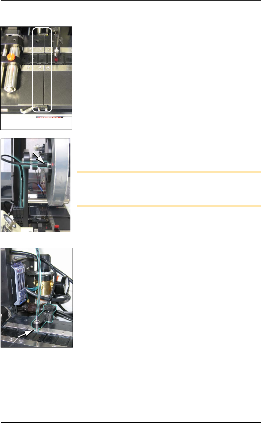
Pocket Empty Sensor and Amplifier
The Pocket Empty sensor alerts the operator when a pocket is empty
as the device tape approaches the cover taping location. This is the
middle sensor in Figure 4-32 on page 4–58.
Adjust the Pocket-Empty Sensor as follows:
1. Set the track width for the target device tape
A) loosen the two Track Width Lock knobs,
B) pull or push the side nearest the operator to correct width,
C) tighten lock knobs.
2. Load a roll of device tape onto the spindle and into the track.
3. Loosen the knob on the left side of the Pocket Empty Sensor
bracket to adjust the height above the tape. Retighten.
4. Loosen the knob on top to center the sensor on the tape.
Retighten.
5. Advance the tape until a pocket with a device in it is centered
under the sensor.
6. Ensure that the Output Selector mode on the middle amplifier is
set to D.ON by pressing the Mode button. (There may be an
L/D ON button or toggle to change the mode.)
7. Press and release the SET button in the right amplifier.
8. Remove the device from the tape pocket.
The Track Jam sensor

Maintenance ■ Tape Output System
4—60 Data I/O • 096-0640-001B
back
9. Press and release the SET button again.
Note: The Pocket-Empty Sensor must be reset for each new
device type to be taped.
■ Dual Tray Feeder ◘ Cleaning and Inspecting the Dual Tray Feeder
PSV7000 Owner’s Manual 4—61
back
Dual Tray Feeder
The Automatic Data I/O Dual Tray Feeder is optional equipment to
the PSV7000 System. It is a high-speed tray exchanger, delivering
JEDEC trays to pick and place positions.
Information not found here, but important, can be found in the Tray
Feeder Operation Manual, such as the location of possible pinch points.
Cleaning and Inspecting the Dual Tray
Feeder
[Data I/O Dual Tray Feeder Tray Feeder only]
1. Stop or Pause a job if one is running.
2. Check the automatic Tray Feeder for damaged or broken parts
and replace as necessary.
3. Visually inspect the shuttle belts for dirt, nicks, or other signs of
damage.
4. If the shuttle belts are dirty, clean with dry, compressed air and
wipe with a dry, lint-free cloth and isopropyl alcohol.
5. Check that the black teflon strips on both long, inside walls are
clean. Clean with a dry, lint-free cloth and isopropyl alcohol.
6. Check that the shuttle/elevator is clean and that trays lay flat.
For more information, see
the Tray Feeder Manual
that came with your system.