PSV7000_ Owners Manual_096-0460-001B - 第24页
Introduct ion ■ Machine Components 1—10 Data I/O • 096-0460-001B back Machine Components The PSV7000 System has many compone nts, or subassemblies, that work together . Refer to the figure below to locate primary compo- …

■ System Description ◘ PSV7000 Specifications
PSV7000 Owner’s Manual 1—9
back
PSV7000 Specifications
Specifications are without optional equipment.
1
Since the monitor arm rotates, length and width dimensions can be
adjusted inversely, up to 13 cm (5 inches). For example, if you sub-
tract 13 cm from length, then add 13 cm to width.
FACILITIES
Supply Air Pressure clean, dry, oil-free air at
5.5–8.2 Bar (551–827 kilopascals)
(80–120 PSI)
Air Flow 85 liters/minute (3 SCFM) constant
AC Input Voltage 208–230 VAC, single phase
AC Input Frequency 50–60 Hz
AC Input Power (max) 15 Amps (with all options)
PSV7000 DIMENSIONS
Length (including monitor)
1
178 cm (70 inches)
Width (including monitor)
1
178 cm (70 inches)
Height: machine (doors closed)
then add [light tower]
150 cm (59 inches) +
[48 cm, 19 in.]
Weight (no optional equipment) 227 kg (500 lbs)
ENVIRONMENT
Operating Temperature +13° to +30° C (+55° to +86° F)
Relative Humidity 35% to 90% non-condensing
Sound level
≤ 80 dB (without tube vibrators)
OTHER
Handler PC Operating System Windows® 7 Professional, 64-bit
Monitor 15 inch LCD Touchscreen
Introduction ■ Machine Components
1—10 Data I/O • 096-0460-001B
back
Machine Components
The PSV7000 System has many components, or subassemblies, that
work together. Refer to the figure below to locate primary compo-
nents.
Component Descriptions
Light Tower
Allows monitoring the status of the PSV7000 System from a distance
while the system is processing devices. See Light Tower Interpretation
in the Operator’s Manual for a complete description of lamp colors
and significance.
Gantry
Travels along X- and Y-axes moving the PNP head to different loca-
tions within the work envelope.
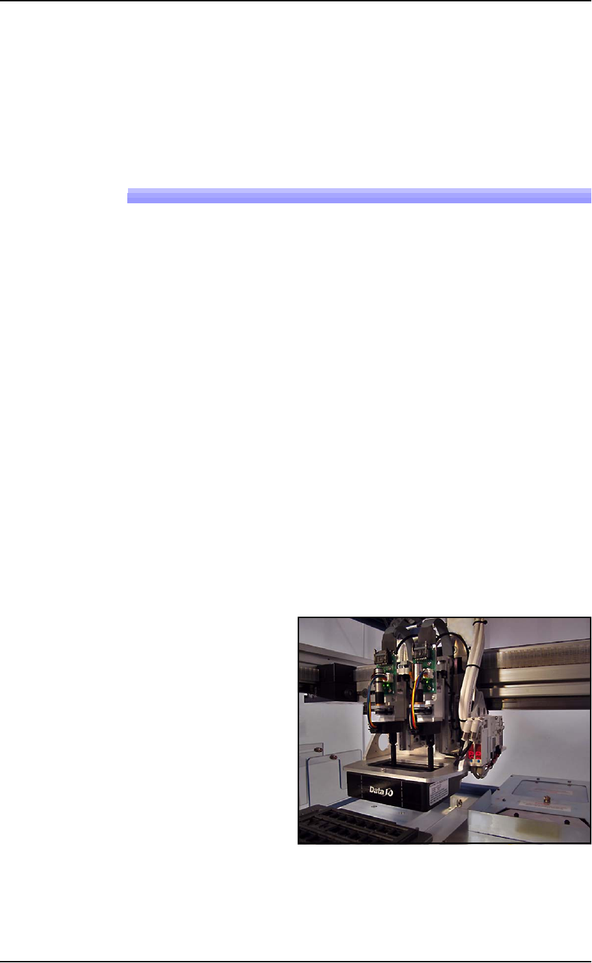
Pick and Place Head (PNP Head)
The PNP head is responsible for moving devices to and from their
respective stages within the workspace. It moves devices in four axes,
X, Y, Z and R.
The PNP head uses different sized probe tips to accommodate the
great number of device types that are available. See Installing the Cor-
rect Probes in the Operator’s Manual. During operation, vacuum at
each probe holds a device. Vacuum sensors detect whether or not a
device is present on a probe tip.
Figure 1-4: The PSV7000 PNP head.
■ Machine Components ◘ Component Descriptions
PSV7000 Owner’s Manual 1—11
back
The probes each pick up a device and move it to a programming
socket. To place devices at target locations, a probe lowers, vacuum is
turned off and blow-off air is momentarily turned on.
WARNING: Collision hazard! The gantry system and associated
components move with high speed and force, and have the
potential to cause great bodily harm. Do not bypass the safety
interlocks or operate the with the safety doors open or removed.
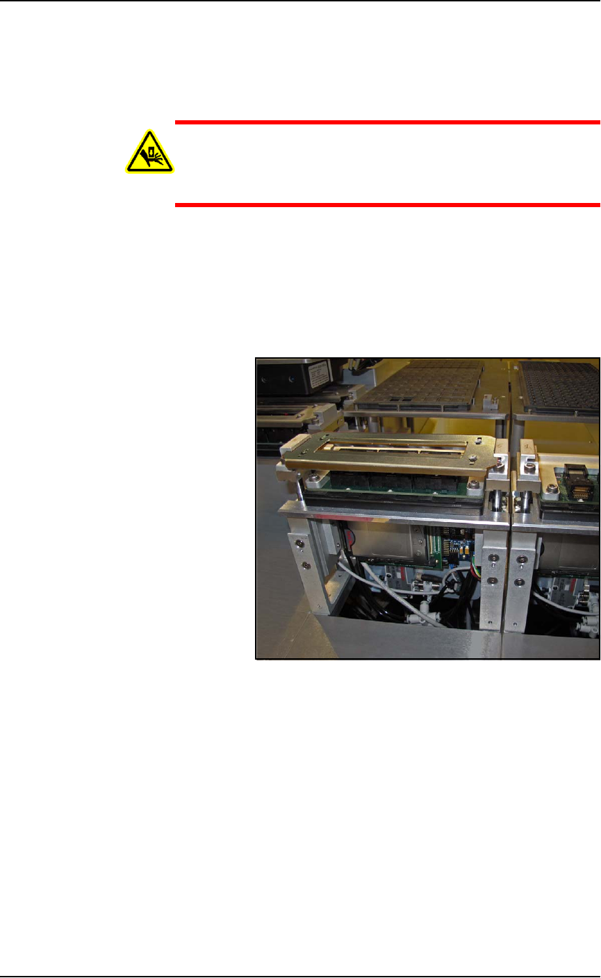
Programmers
Data I/O’s FlashCORE III programming modules are one of the
fastest programmer architectures available. FLASHCORE Pro-
grammer Modules in the PSV7000 include pneumatic socket actua-
tion.
Figure 1-5: A FlashCORE Programmer with a Socket Adapter and
Actuator Plate installed on it. The front cover plate is removed.
Device-Position (Vision) System
PSV7000 uses a Laser-guided Device-position Sensor attached to the PNP
head for precise picking and placing.
Static Tray Mount
Using positioning pins and a magnet, JEDEC and non-JEDEC stan-
dard trays are held firm for the PNP head to pick devices and return
them after processing.