PSV7000_ Owners Manual_096-0460-001B - 第26页
Introduct ion ■ Machine Components 1—12 Data I/O • 096-0460-001B back Figure 1-6: Static tra ys. Not e that the bev eled corner is at the near right, adjacent t o the sensor . Handler Computer The on-board Handler comput…
■ Machine Components ◘ Component Descriptions
PSV7000 Owner’s Manual 1—11
back
The probes each pick up a device and move it to a programming
socket. To place devices at target locations, a probe lowers, vacuum is
turned off and blow-off air is momentarily turned on.
WARNING: Collision hazard! The gantry system and associated
components move with high speed and force, and have the
potential to cause great bodily harm. Do not bypass the safety
interlocks or operate the with the safety doors open or removed.
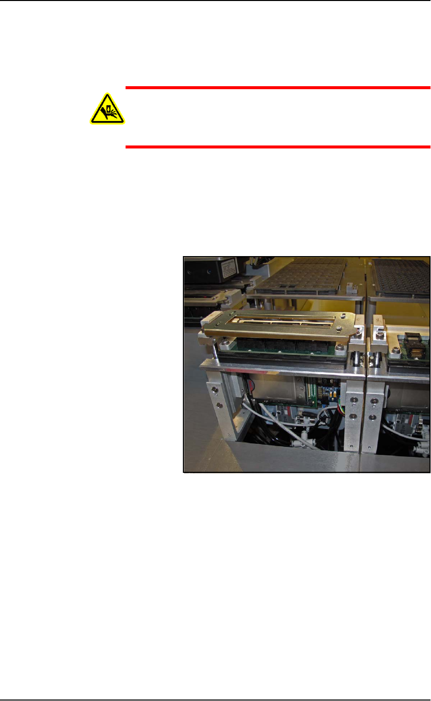
Programmers
Data I/O’s FlashCORE III programming modules are one of the
fastest programmer architectures available. FLASHCORE Pro-
grammer Modules in the PSV7000 include pneumatic socket actua-
tion.
Figure 1-5: A FlashCORE Programmer with a Socket Adapter and
Actuator Plate installed on it. The front cover plate is removed.
Device-Position (Vision) System
PSV7000 uses a Laser-guided Device-position Sensor attached to the PNP
head for precise picking and placing.
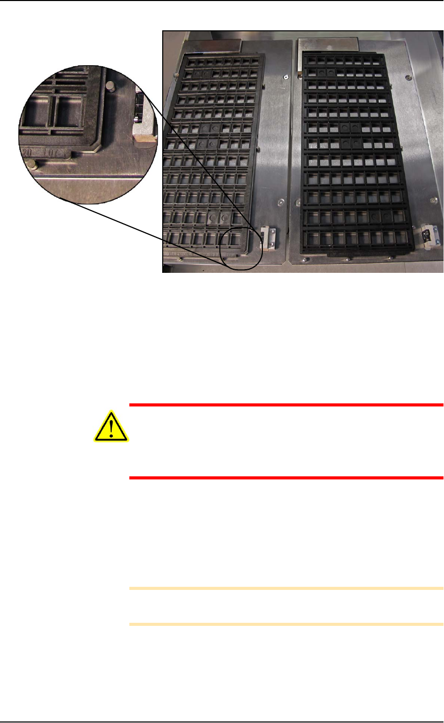
Static Tray Mount
Using positioning pins and a magnet, JEDEC and non-JEDEC stan-
dard trays are held firm for the PNP head to pick devices and return
them after processing.
Introduction ■ Machine Components
1—12 Data I/O • 096-0460-001B
back
Figure 1-6: Static trays. Note that the beveled corner is at the near
right, adjacent to the sensor.
Handler Computer
The on-board Handler computer hosts TaskLink software and the
AH700 software, and monitors all sensors. The computer contains a
CPU that runs Microsoft Windows 7 Operating System (at time of
release).
CAUTION: Possible machine damage! Adding software to the
PSV7000 System can cause damage or cause the system to oper-
ate improperly. Adding software without specific instruction from
Data I/O Customer Support will void the warranty and may incur
service charges if subsequent service is required.
Keyboard and Touch Screen
Both methods of input are available for operation. With the touch-
screen, tap the screen with a finger only, not sharp objects such as
pens or pencils.
Note: Throughout this Owner’s Manual, the term click is also
used to mean tap when using the touch screen monitor.
■ Machine Components ◘ Component Descriptions
PSV7000 Owner’s Manual 1—13
back
ESD Strap Connection
When operators plug an antistatic wrist strap into the ESD strap con-
nection, it reduces the risk of damage to devices and Socket Adapters
from electrostatic discharge (ESD).
Safety Doors
Designed to protect against injury and damage from the PNP head
movement, the safety doors are an important safety feature, stopping
the gantry when they are opened.
For more information see Safety Door with Interlocks on page 1-5.
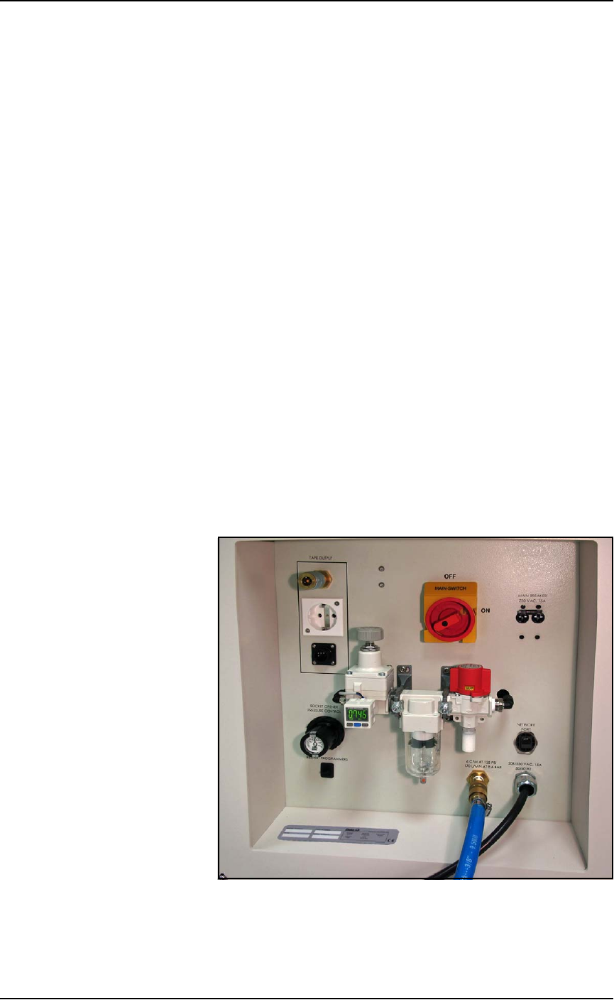
Power Panel
The Power Panel is on the lower left side of the machine.
Connections
The Power Panel allows for the attachment of AC power and air.
Optional connections:
• you can connect an ethernet cable for internet connection
• the Tape Output module connects here also.
Controls
Mounted on the Power Panel are the main power switch and the
main air regulator and filter. There is a second regulator with a sepa-
rate gauge for adjusting socket opener pressure. See Adjusting the
Socket Actuator Air Pressure on the Programmers on page 4-9.
Figure 1-7: Power Panel on the left side of the machine.