PSV7000_ Owners Manual_096-0460-001B - 第28页
Introduct ion ■ Machine Components 1—14 Data I/O • 096-0460-001B back Circuit Break ers There is one circuit breaker and one toggle switch on the P ower Pa n e l . The toggle switch allows shutting off pow er to only the…
■ Machine Components ◘ Component Descriptions
PSV7000 Owner’s Manual 1—13
back
ESD Strap Connection
When operators plug an antistatic wrist strap into the ESD strap con-
nection, it reduces the risk of damage to devices and Socket Adapters
from electrostatic discharge (ESD).
Safety Doors
Designed to protect against injury and damage from the PNP head
movement, the safety doors are an important safety feature, stopping
the gantry when they are opened.
For more information see Safety Door with Interlocks on page 1-5.
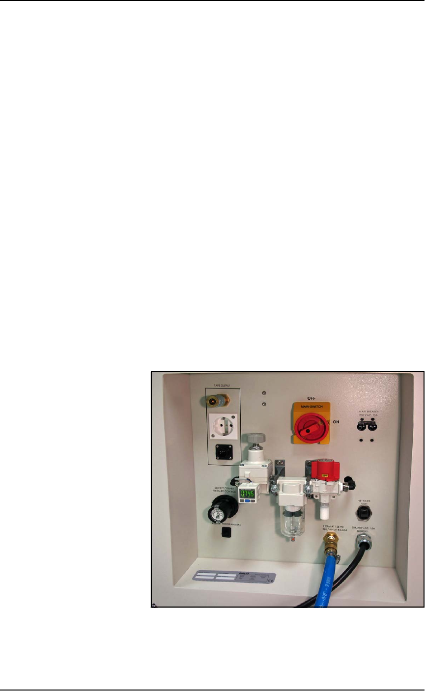
Power Panel
The Power Panel is on the lower left side of the machine.
Connections
The Power Panel allows for the attachment of AC power and air.
Optional connections:
• you can connect an ethernet cable for internet connection
• the Tape Output module connects here also.
Controls
Mounted on the Power Panel are the main power switch and the
main air regulator and filter. There is a second regulator with a sepa-
rate gauge for adjusting socket opener pressure. See Adjusting the
Socket Actuator Air Pressure on the Programmers on page 4-9.
Figure 1-7: Power Panel on the left side of the machine.
Introduction ■ Machine Components
1—14 Data I/O • 096-0460-001B
back
Circuit Breakers
There is one circuit breaker and one toggle switch on the Power
Panel.
The toggle switch allows shutting off power to only the program-
mers.
Optional Equipment Descriptions
Numerous hardware options can be purchased with PSV7000, most
of which are the various input and output modes. Some of the
non-input/output options are 3D-Coplanarity, laser marking for
devices, and output reel labelling.
(Optional) Labelling Device Reels
A Label Printer can be used to mark output reels for identification.
Figure 1-8: Paper Labeler. (Your labeler may look different.)
Laser Marking Devices
The Laser Marking System uses an ultra compact IR Laser to mark
devices. The laser applies a customer-defined mark. Lighter Software is
supplied with the laser for creating marking files. The laser marking
system operates as a Class 1 laser system, with a class 4 embedded
laser (CDRH classification), and therefore uses integrated interlocks
to prevent the laser from firing while any cover is open. The laser
should never be operated without safety covers in place. Observe all
warnings regarding laser usage.
For additional safety information, see Laser Safety on page 1-20.
Main Circuit Breaker 230 V 15 A
■ Machine Components ◘ Optional Equipment Descriptions
PSV7000 Owner’s Manual 1—15
back
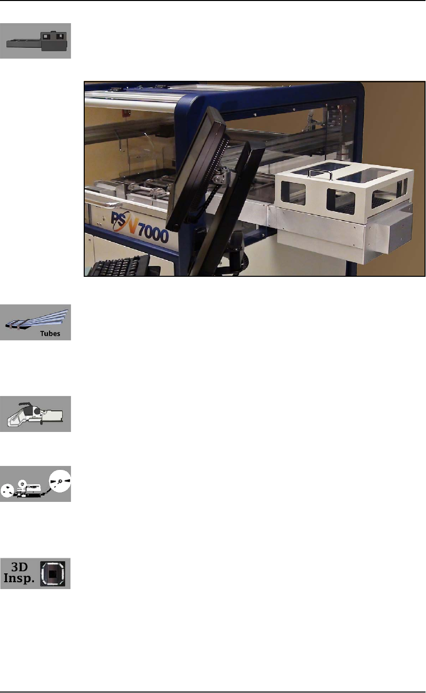
(Optional) Automatic Tray Feeder
Designed to automatically supply trays full of devices to the
PSV7000 System, the Data I/O Dual Tray Feeder accepts up to twenty
thin or thick JEDEC trays.
Figure 1-9: Data I/O Dual Tray Feeder.
(Optional) Tube Input and Output Modules
The input tube holds blank devices and the output tube collects
devices after programming. Vibration mechanisms keep devices
sliding freely by gently vibrating the tubes to reduce the likelihood of
device jams. Vibration adjustment controls are located on the front of
the PSV7000 System.
(Optional) Tape Input Module
The tape input module is a chip feeder which provides devices for
programming. Each device is picked from a carrier tape pocket and
placed into a programming socket.
(Optional) Tape Output Module
The tape output module, mounted on the Option Bay, uses a reel of
empty carrier tape to hold devices after they are programmed. Pro-
grammed devices are placed into empty pockets on the carrier tape.
The carrier tape advances through either a heat seal or pressure seal
unit that applies cover tape to the carrier tape.
(Optional) 3D-Coplanarity Inspection
The 3D Coplanarity Inspection System checks for accurate 3-dimen-
sional positions of all the leads on a integrated circuit and can detect
lead burrs. The 3D System inspects devices after programming is
complete to make sure device contacts are within customer-defined
tolerance. The inspection system uses its own computer installed into
PSV7000.