PSV7000_ Owners Manual_096-0460-001B - 第37页
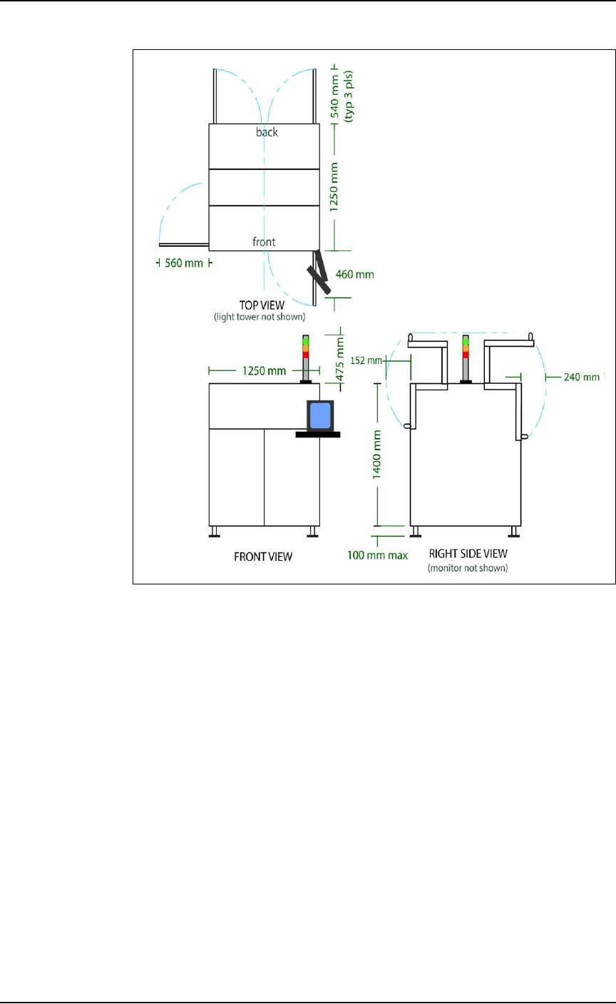
■ Room Considerations ◘ Access Space PSV7000 Owner’s Manual 1—23 back Figure 1-13: Maximum envelope of PS V7000 without optional equipment such as marking, T ape-In or T ape Output (to scale).
■ Room Considerations ◘ Access Space
1—22 PSV7000 Owner’s Manual
The intended area for installation must:
• allow at least one meter (39 inches) of clearance on all sides of
the machine for opening access panels as well as repairing and
replacing subassemblies,
• provide a solid foundation (for example, a concrete floor). The
machine contains a fast-moving gantry with much mass. The
area for it must be stable, solid, and mostly level prior to installa-
tion. If this is not achievable, consider installing the system at
another location.
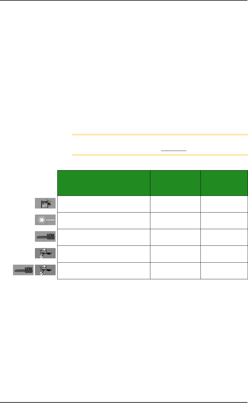
The table below lists recommended, minimum envelope size deter-
mined by the 1 meter access space required on each side:
Minimum Physical Envelope
Note: The numbers below do not include ventilation requirements
discussed in the previous heading Ventilation.
For example, a PSV7000 System with a Data I/O Dual Tray Feeder
requires a minimum physical area of 3.4 meters deep x 3.8 meters
wide for easy access.
Machine Configuration
L (depth) x W
(Y-axis x X-axis)
L (depth) x W
+ 1 m all sides
for access
PSV7000 only
2.4 m x 2.3 m 3.4 m x 3.3
PSV7000 + Laser
2.4 m x 2.3 m 3.4 m x 3.3 m
PSV7000 + Tray Feeder 2.4 m x 2.8 m 3.4 m x 3.8 m
PSV7000 + Tape Out Module with
large reel
2.4 m x 3.3 m 3.4 m x 4.3 m
PSV7000 + Tray Feeder + Tape Out
Module with large reel
2.4 m x 3.8 3.4 m x 4.8
■ Room Considerations ◘ Access Space
PSV7000 Owner’s Manual 1—23
back
Figure 1-13: Maximum envelope of PSV7000 without optional
equipment such as marking, Tape-In or Tape Output (to scale).

Introduction ■ Room Considerations
1—24 Data I/O • 096-0460-001B
back