PSV7000_ Owners Manual_096-0460-001B - 第41页
■ Connecting Facilities ◘ Connecting Air PSV7000 Owner’s Manual 2—3 back Connecting Facilities The PSV7000 requires two external services: pressurized air and elec- trical power . It also allows one op tional connection …
Setup ■ Machine Installation
2—2 Data I/O • 096-0460-001B
back
Leveling
When the PSV7000 is at the desired location, adjust the feet to level it.
WARNING: Possible machine damage or personal injury!
Instability such as vibrating, walking, or rocking, may occur if
fewer than four of the installed feet make suitable contact
with the floor, or if the leg locknuts are not tightened against
the frame.
Only the adjustable feet provided on the PSV7000 Machine
should be used for leveling. Do not use shims to assist in level-
ing.
■ Connecting Facilities ◘ Connecting Air
PSV7000 Owner’s Manual 2—3
back
Connecting Facilities
The PSV7000 requires two external services: pressurized air and elec-
trical power. It also allows one optional connection to an Internet via
a Network connection. These services connect to the PSV7000
Machine at the Power Panel located on the left side of the machine.
With the two required services, the machine creates all the unique
electrical voltages needed as well regulating pneumatic pressure for
all systems within the machine.
Connecting Air
The machine requires clean, dry, oil-free air from an industrial grade
compressor.
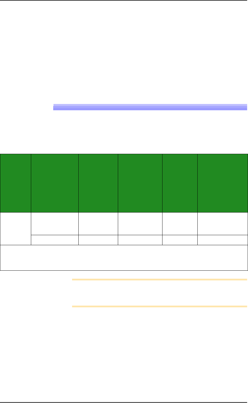
PSV7000 Air Requirements Table
Note: If the compressor cannot maintain the correct air pressure
and stable air volume, PSV7000 System performance will be
affected and may damage devices.
System Air Volume
@ Air
Pressure at
inlet
regulator on
PSV7000
Supply Air
Min. Air
Tube
Length
1
Customer
supplies a
primary
filter/regulator
required between
factory
compressor and
PSV7000
2
—Metric 85 L/minute
[.084 Nm3/min],
constant
5.5 ±0.3 Bar 5.5 - 8.2 Bar 3 Meters 10 micron
—US 3 SCFM constant 80 ±5 PSI 80 to 120 PSI 10 Feet 10 micron
1
This external air line must allow the supplied air to cool sufficiently so that water vapor in the air
condenses and can be extracted.
2
The air filter on the Power Panel is a secondary filter only.
Setup ■ Connecting Facilities
2—4 Data I/O • 096-0460-001B
back
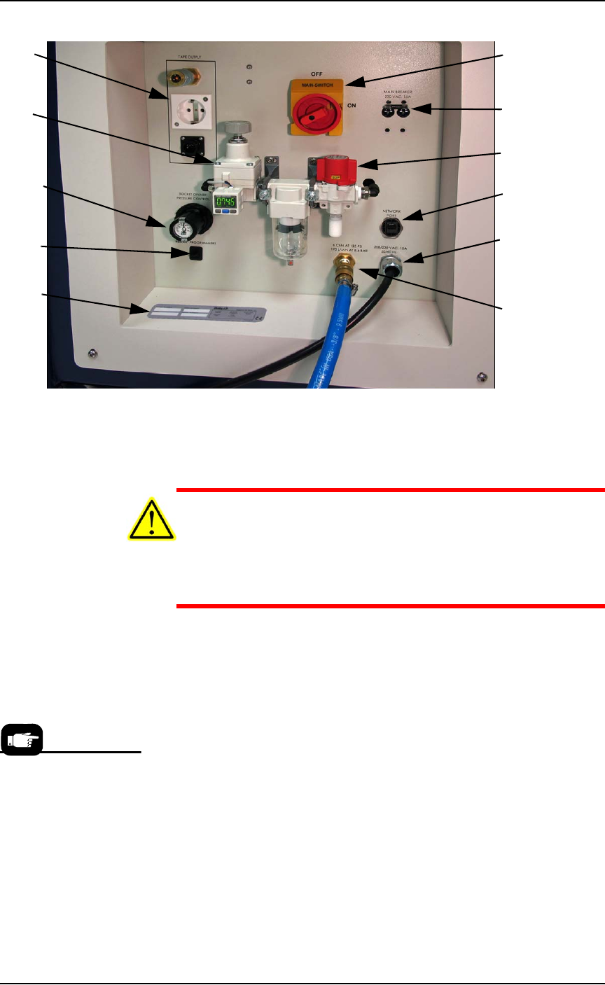
Figure 2-1: The Power Panel on the left side of the machine.
Connect air to PSV7000 at the main regulator and filter.
See Figure 2-1 for the location of the external air line connection.
CAUTION: Possible air system damage! Oil, excessive moisture, or
poorly filtered air will obstruct the system’s internal air pathways,
affect performance, and void the warranty related to air system
failure. If oil or excessive moisture is detected, contact Data I/O
Customer Support or a local Data I/O approved service represen-
tative.
Main Air Pressure Gauge
The main pressure regulator is set at the factory and cannot be
changed without the password. See PSV7000 Air Requirements Table on
page 2-3 for the factory setting.
When air pressure is within range, the regulator readout is green. If
air pressure is above or below the acceptable range, the readout dis-
plays red. If it is red (out of range), contact Data I/O Support or a
qualified service technician.
Main Power
Switch (lockout
capable)
Main Breakers,
230 VAC, 15A
Air Shut off
valve.
8P8C Ethernet
connection
Power cable
(does not discon-
nect here)
Air Connection
Tape Output
Module con-
nections
Main regula-
tor and filter;
see specs on
previous page.
Socket Opener
Pressure Con-
trol
Programmer
Power Restart
Serial Number
If there is low air pressure
the monitor may display a
message reading
No air.