PSV7000_ Owners Manual_096-0460-001B - 第43页
■ Connecting Facilities ◘ Connecting Electrical Power PSV7000 Owner’s Manual 2—5 back Connecting Electrical P ower WARNING: Electric shock haza rd! Personal injury could be caused from high leakage el ectrical curren t f…
Setup ■ Connecting Facilities
2—4 Data I/O • 096-0460-001B
back
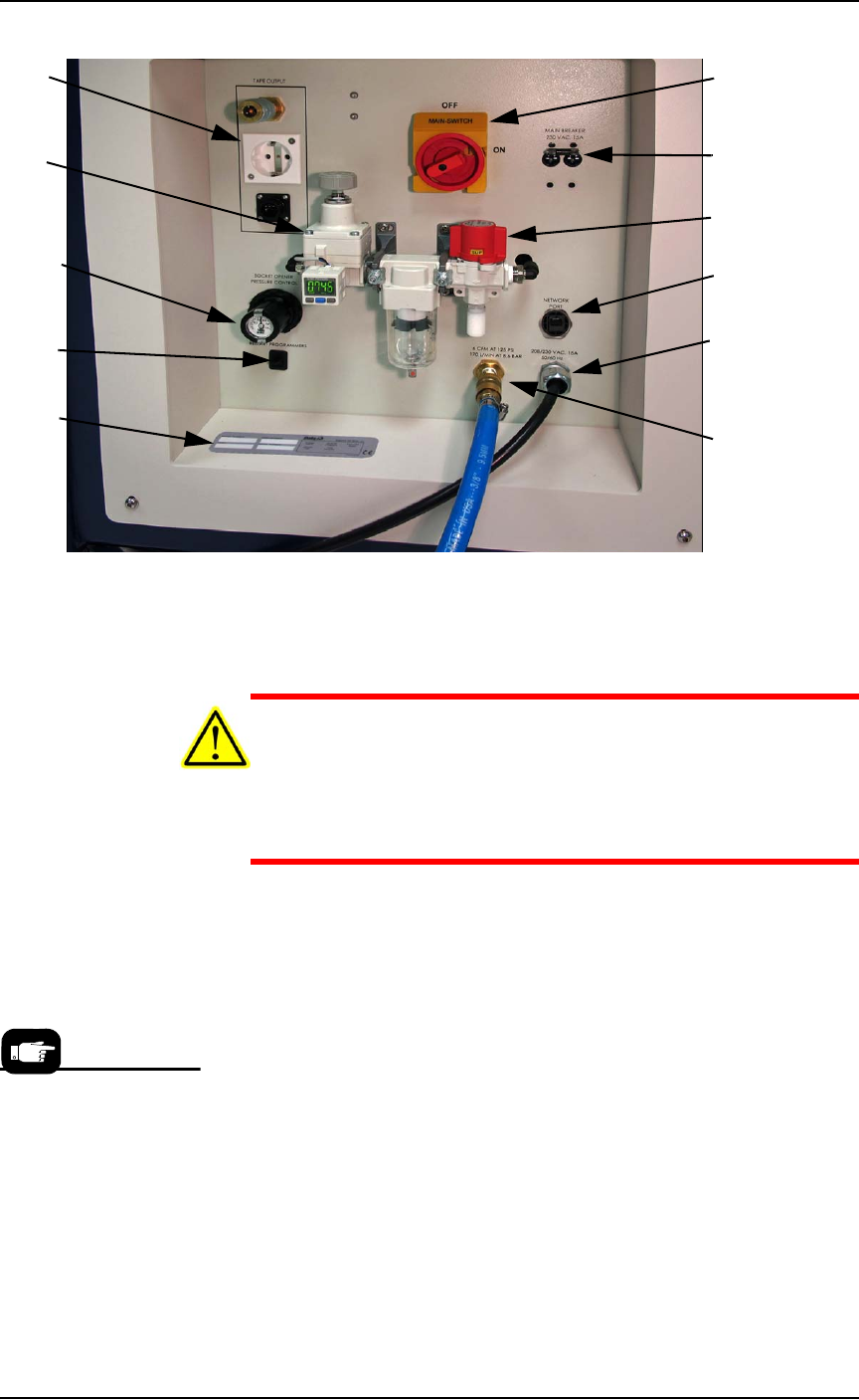
Figure 2-1: The Power Panel on the left side of the machine.
Connect air to PSV7000 at the main regulator and filter.
See Figure 2-1 for the location of the external air line connection.
CAUTION: Possible air system damage! Oil, excessive moisture, or
poorly filtered air will obstruct the system’s internal air pathways,
affect performance, and void the warranty related to air system
failure. If oil or excessive moisture is detected, contact Data I/O
Customer Support or a local Data I/O approved service represen-
tative.
Main Air Pressure Gauge
The main pressure regulator is set at the factory and cannot be
changed without the password. See PSV7000 Air Requirements Table on
page 2-3 for the factory setting.
When air pressure is within range, the regulator readout is green. If
air pressure is above or below the acceptable range, the readout dis-
plays red. If it is red (out of range), contact Data I/O Support or a
qualified service technician.
Main Power
Switch (lockout
capable)
Main Breakers,
230 VAC, 15A
Air Shut off
valve.
8P8C Ethernet
connection
Power cable
(does not discon-
nect here)
Air Connection
Tape Output
Module con-
nections
Main regula-
tor and filter;
see specs on
previous page.
Socket Opener
Pressure Con-
trol
Programmer
Power Restart
Serial Number
If there is low air pressure
the monitor may display a
message reading
No air.
■ Connecting Facilities ◘ Connecting Electrical Power
PSV7000 Owner’s Manual 2—5
back
Connecting Electrical Power
WARNING: Electric shock hazard! Personal injury could be
caused from high leakage electrical current from the main
power cable. An Earth (ground) connection is essential
before connecting power.
Required power is provided through a supplied 3-wire power cable
with one end terminated in an electrical plug as required by the cus-
tomer’s facility. For power specifications, see PSV7000 Specifications
on page 1-9. For cable location see Figure 2-1 on page 2–4.
(Optional) Connecting an Ethernet
Cable
A Network connection is on the Power Panel. Plug in an Ethernet
cable. Refer to Figure 2-1 on page 2–4.
Network settings are described in (Optional) Network Settings on page
2-8.
CAUTION: Possible PC virus hazard! The PSV7000 System has no
antivirus software installed from the factory. Prior to connecting
to a network, Data I/O recommends installing antivirus software.
To install antivirus software refer to (Optional) Installing Antivirus
Software on page 2-8.
Setup ■ Applying Power for the First Time
2—6 Data I/O • 096-0460-001B
back
Applying Power for the First Time
Before the PSV7000 System is turned on for the first time, ensure the
following:
The external air line is connected, and the main air valve is open.
All E-Stop buttons are in the released (operating) positions (refer
to Emergency Stop (E-Stop) Buttons on page 1-4 for location).
All safety doors and access doors are closed.
The circuit breakers on the Power Panel on the left side of the
machine are in the ON (UP) position.
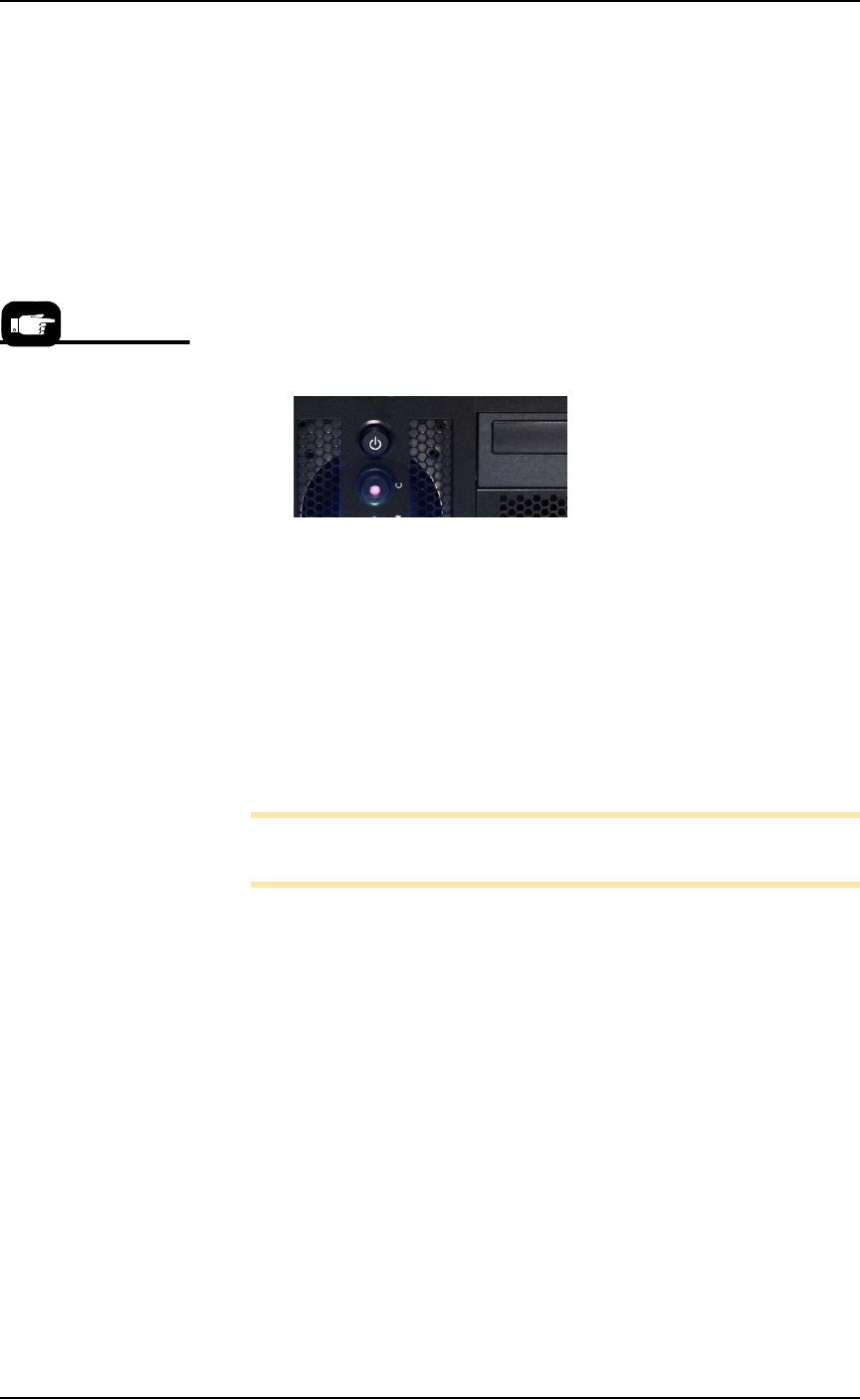
The power switch on the Handler Computer is set to the ON
position (although it will not have power yet). The rocker switch
is ON when tipped to the down position.
(Optional) The Socket Adapters required for the job have been
installed on all necessary programmer sites. See Installing Socket
Adapters in the Operator’s Manual for more information.
When satisfied, rotate the main power switch on the Power Panel to
the ON position (clockwise).
After power is applied, verify that no obvious failures or electrical
anomalies occur. Verify that the Handler Computer starts properly
and displays a network log-on dialog.
Note: If electrical or mechanical problems are noted, turn OFF the
PSV7000 System and notify Data I/O Customer Support.
At the Microsoft Log-on window, click the user profile (usually
labeled MFG) to complete the startup procedure.
Normal operating pro-
cedure never requires the
Handler Computer
power switch to be
turned off manually.