PSV7000_ Owners Manual_096-0460-001B - 第48页
Setup ■ Setting Up Input and Output Media 2—10 Data I/O • 096-0460-001B back Setting Up Input and Output Media There are many options for device input and output. One option for input and one for ou tput must be set up o…
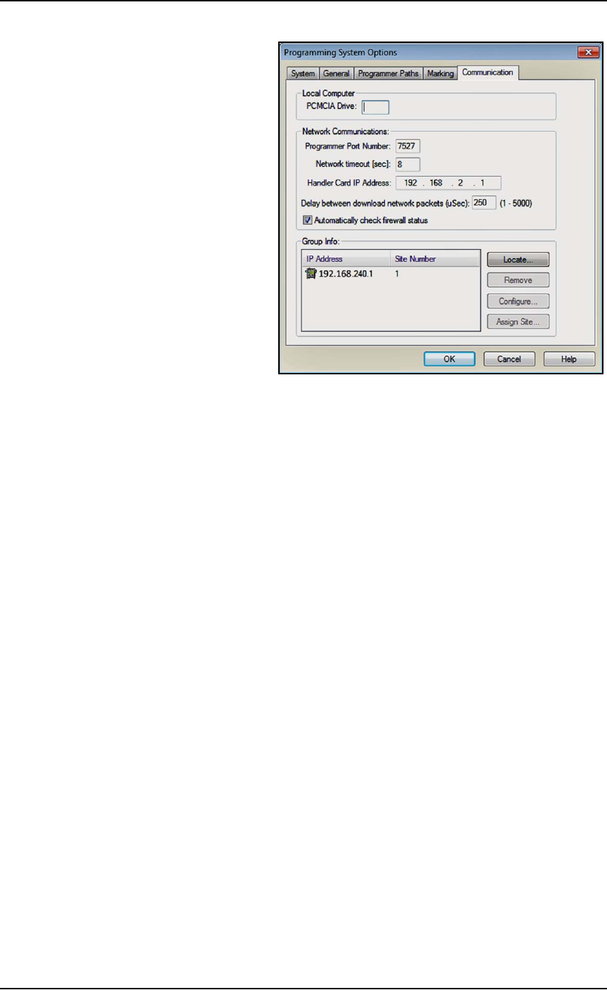
■ Applying Power for the First Time ◘ (Optional) Network Settings
PSV7000 Owner’s Manual 2—9
back
Figure 2-3: TaskLink Communication Tab displays IP Addresses and
site numbers.

Setup ■ Setting Up Input and Output Media
2—10 Data I/O • 096-0460-001B
back
Setting Up Input and Output Media
There are many options for device input and output. One option for
input and one for output must be set up on the PSV7000 Machine for
your target job. Further, the setup must correspond with the current
software, such as the Job file, winAH400.ini file, and printer file (laser
or label marker).
These input/output media are described in this section:
•Static Tray (below)
• Dual Automatic Tray Feeder, page 2-12
• Tube Input/Output Vibration System, page 2-18
• Tape Output Module, page 2-21
Note: The Tape Input feeder installation is covered in the PSV7000
Operator’s Manual.
About Static Tray Input and Output
The standard configuration for the PSV7000 System is static tray
input and static tray output media. The latest tray mounting configu-
ration uses two rows of locating pins and a magnet. Specific steps for
installing trays are described in the PSV7000 Operator’s Manual.
Note: Make sure that the correct devices for the target job are
loaded into the input tray and that they have the correct pin 1 ori-
entation. (If pin 1 orientation doesn’t match pin 1 that is set in the
Package File it must be corrected).
Pin 1 on Data I/O sockets is almost always toward the far side of
the Socket Adapter (the back of the machine).
Remember that tray arrangement affects:
•the Setup window > Options tab which must be set to match the
workspace setup (covered in the Operator’s Manual).
• the Package File which must be taught the Tray locations (cov-
ered later in Chapter 3 of this manual).
Removing Tray Platforms
Tray Platforms can be removed to support different mediums such as
to install an automatic tray feeder.
Requirements
Metric hex key set.
■ Setting Up Input and Output Media ◘ About Static Tray Input and Output
PSV7000 Owner’s Manual 2—11
back
To remove a Tray Platform:
1. Shut OFF the PSV7000 System. See Shutting Down the
PSV7000 System on page 2-7.
2. Disconnect the tray sensor—
2a. Remove two sensor bracket screws (2.5 mm).
2b. Lift the bracket up and remove the two screws securing the
sensor to the bracket (1.5 mm).
Note: Best practice is to re-attach the sensor screws to the
bracket, and the bracket to the platform so parts don’t get
lost.
3. Open the front or back access door and remove four screws from
the target Tray Platform (3 mm hex key).
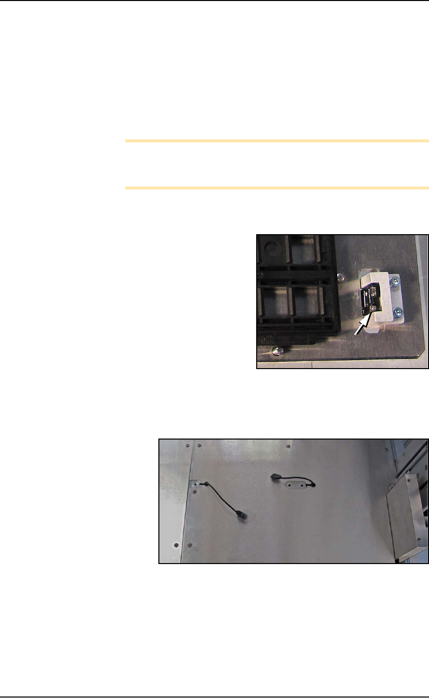
Figure 2-4: Static Tray Sensor and bracket. Two bracket screws shown
(at B). Only one of the sensor screws is visible (arrow).
4. At the work surface, lift the platform up leaving the sensor lie on
the surface.
Figure 2-5: Static Tray sensors left after removing static tray mounts.
To re-install the platform, reverse the steps for removal.
B
B