PSV7000_ Owners Manual_096-0460-001B - 第50页
Setup ■ Setting Up Input and Output Media 2—12 Data I/O • 096-0460-001B back Install R eject Bin Install a reject container for device s failing any process. M any work- space layouts are possible . Generally , a reject …
■ Setting Up Input and Output Media ◘ About Static Tray Input and Output
PSV7000 Owner’s Manual 2—11
back
To remove a Tray Platform:
1. Shut OFF the PSV7000 System. See Shutting Down the
PSV7000 System on page 2-7.
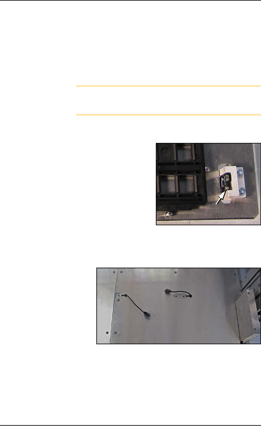
2. Disconnect the tray sensor—
2a. Remove two sensor bracket screws (2.5 mm).
2b. Lift the bracket up and remove the two screws securing the
sensor to the bracket (1.5 mm).
Note: Best practice is to re-attach the sensor screws to the
bracket, and the bracket to the platform so parts don’t get
lost.
3. Open the front or back access door and remove four screws from
the target Tray Platform (3 mm hex key).
Figure 2-4: Static Tray Sensor and bracket. Two bracket screws shown
(at B). Only one of the sensor screws is visible (arrow).
4. At the work surface, lift the platform up leaving the sensor lie on
the surface.
Figure 2-5: Static Tray sensors left after removing static tray mounts.
To re-install the platform, reverse the steps for removal.
B
B
Setup ■ Setting Up Input and Output Media
2—12 Data I/O • 096-0460-001B
back
Install Reject Bin
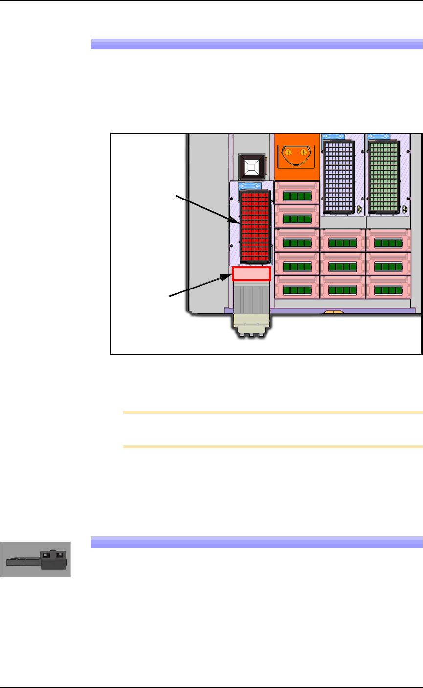
Install a reject container for devices failing any process. Many work-
space layouts are possible. Generally, a reject bin (or box) is placed on
the front left of the workspace as shown in Figure 2-6, on top the Tape
Input media exit chute. However, a box or pad can be placed wher-
ever there is room for it as long as its location is taught in the Package
File.
Figure 2-6: Common locations for the reject tray and bin. Only one is
necessary. The reject bin that comes with the PSV7000 should be
placed as shown.
Note: On the Gantry window, the reject bin or tray is associated
with a yellow position label that reads RTr.
A tray may be used as a reject container versus a bin. Possible layouts
are shown in the above diagram.
Setting Up an Automatic Tray Feeder
The PSV7000 System can be configured with an Automatic Dual Tray
Feeder.
The Tray Feeder must be level to the Gantry and square to the
PSV7000 Machine. For general information about setting it up, see the
Tray Feeder Owner’s Manual that came with your system. Look for
the heading Installation.
Reject Tray
Reject Bin
■ Setting Up Input and Output Media ◘ Setting Up an Automatic Tray Feeder
PSV7000 Owner’s Manual 2—13
back
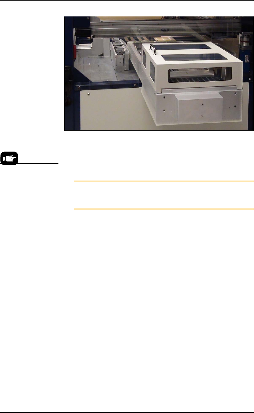
Figure 2-7: The Data I/O Dual Tray Feeder mounted on PSV7000.
The winAH400.ini file requires editing prior to using a Data I/O Dual
Tray Feeder if your PSV7000 Machine has not already been set up for
one at the factory. See the AH700 on-screen Help file for topic Editing
the winAH400.ini file.
Note: When your winAH400.ini file is set to run Automatic Tray
Feeders, before you can run static trays again, the file will need to
be changed back to ModelTray1=STD.
Installing the Tray Feeder
The Data I/O Dual Tray Feeder can only be installed if your PSV7000
was set up for it at the factory or by a Data I/O Service Techncian.
Requirements
• Two people to lift it
•Metric hex key set
• Key to access door
• 12 mm wrench
To install the Data I/O Dual Tray Feeder:
1. Shut OFF PSV7000 power. See Shutting Down the PSV7000 System
on page 2-7.
2. Remove the Input and Output static tray mounts, if installed.
Refer to Removing Tray Platforms on page 2-10.
3. On the right side of the machine, locate the clear rectangular
shield covering the Data I/O Dual Tray Feeder opening.
4. Remove the left screw with a 4 mm hex key and a 12 mm
wrench.
Prior to editing the
winAH400.ini file, make a
backup copy.