PSV7000_ Owners Manual_096-0460-001B - 第53页
■ Setting Up Input and Output Media ◘ Setting Up an Automatic Tray Feed er PSV7000 Owner’s Manual 2—15 back Figure 2-9: The Data I/O Dual T ray F eeder mounting bars (arrows). Views from the back of the mac hine. (Note t…
Setup ■ Setting Up Input and Output Media
2—14 Data I/O • 096-0460-001B
back
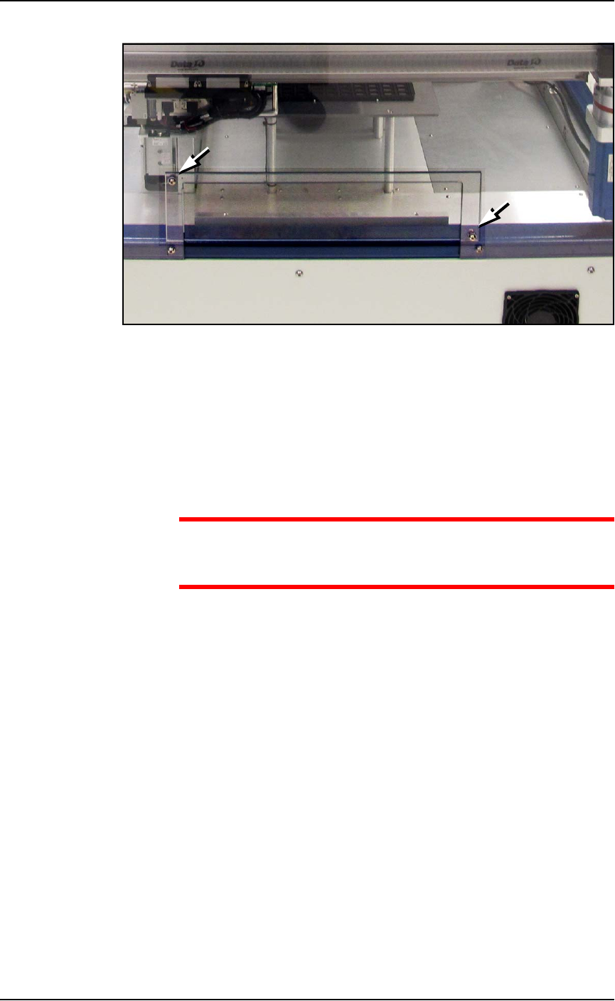
Figure 2-8: The safety shield for the Data I/O Dual Tray Feeder has not
yet been rotated out of the way. Note that the tray mounting plates
(shown here) would NOT be installed at this time.
5. Loosen the lower right screw.
6. Rotate the shield up 90° clockwise and fasten in place at the
extra hole with the screw removed earlier.
7. Get the Data I/O Dual Tray Feeder fasteners ready, and a 5 mm
hex key.
CAUTION: Heavy equipment! The Data I/O Dual Tray Feeder
weighs 29 kg (64 lb). Two people are required to lift it. A third
person is needed to attach fasteners. Use caution.
8. With two people lifting the Data I/O Dual Tray Feeder, slide the
nose into the shield opening and in far enough to rest on the
mount bar inside.
Refer to Figure 2-9 below.
■ Setting Up Input and Output Media ◘ Setting Up an Automatic Tray Feeder
PSV7000 Owner’s Manual 2—15
back
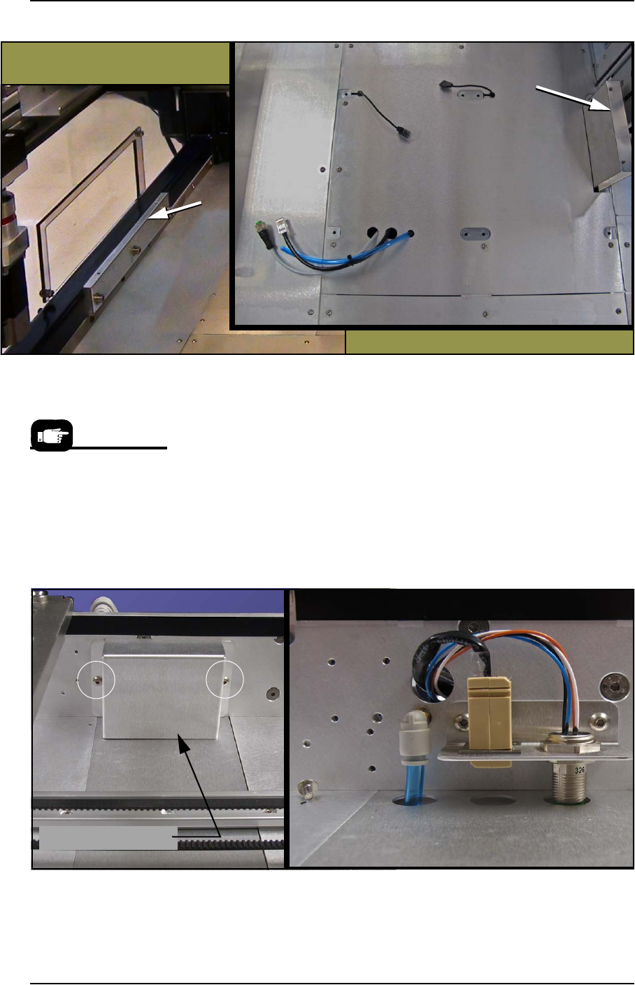
Figure 2-9: The Data I/O Dual Tray Feeder mounting bars (arrows).
Views from the back of the machine. (Note that the shield has not been
rotated out of the way in this image.)
9. Screw in two screws (5 mm hex key) into each of the two mount-
ing bars to secure the feeder.
10. Remove the utilities connection cover; two screws (2.5 mm hex
key).
11. Plug in the three utilities: air, electrical, and ethernet.
The air connection is a One-Touch fitting.
Rotate the electrical connector until it slides into the socket, then
screw the ring up.
Figure 2-10: The Data I/O Dual Tray Feeder utilities connection cover
has two screws (circled). The Ethernet cable is not connected in this
view.
Utilities cover is removed
Utilities Cover
Refer to the following
two figures for Tray
Feeder connections.
Setup ■ Setting Up Input and Output Media
2—16 Data I/O • 096-0460-001B
back
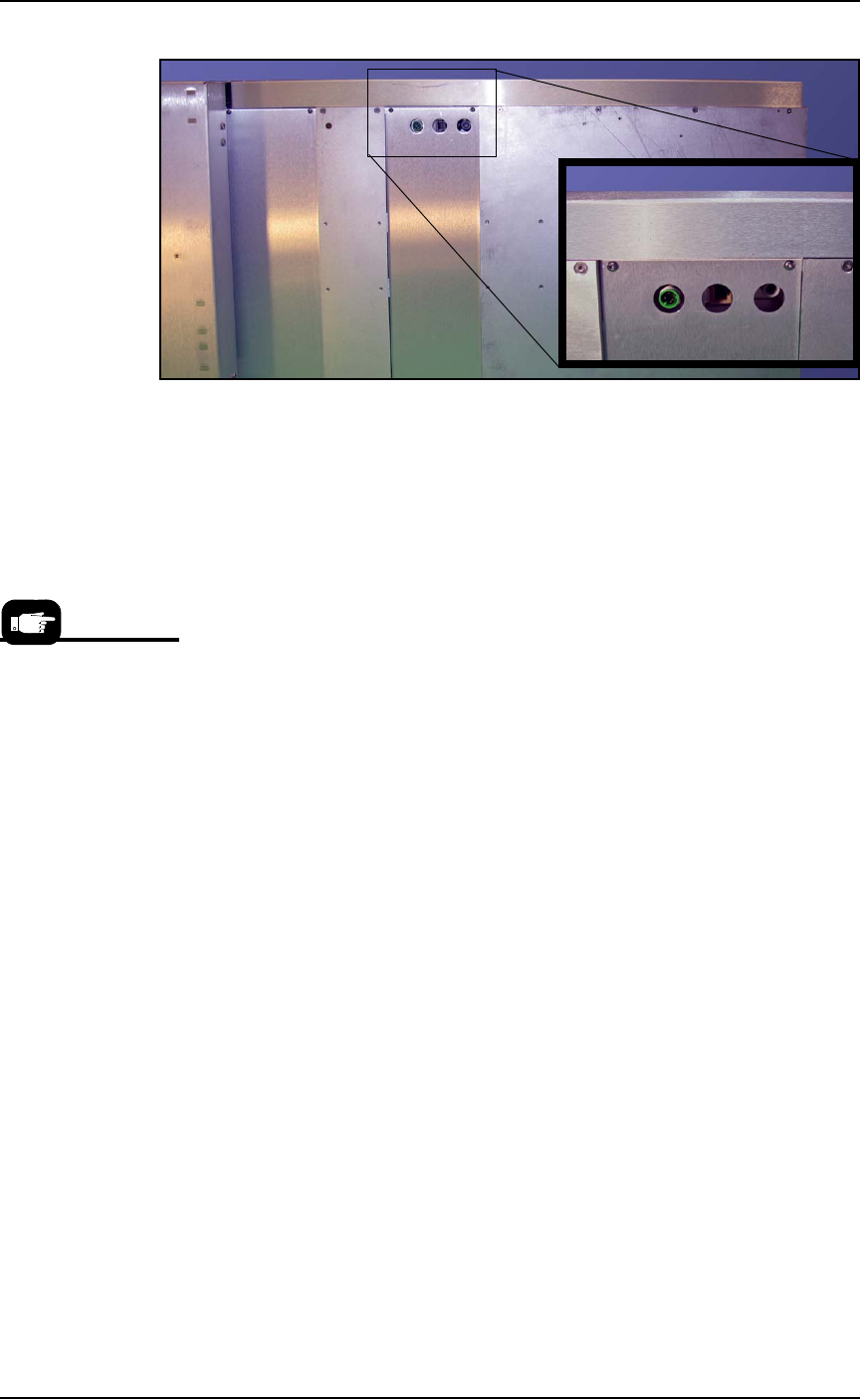
Figure 2-11: Connection for the Data I/O Dual Tray Feeder: electrical,
Ethernet, and air (left to right).
12. Re-attach the utilities cover.
Very basic operating instructions are covered in the PSV7000 Opera-
tors Manual. Complete instructions are covered in the Data I/O Dual
Tray Feeder Owner’s Manual.
Tray Arrangements
You can use a spare tray with an Automatic Tray Feeder (ATF). When
tray position two is designated as a spare static tray, the devices from
that spare tray are used to replace rejected devices. They are also
used during a tray change.
For possible configurations, see the chart on the following page.
A ‘spare tray’ is also
referred to as an ‘aux-
iliary static tray.’