PSV7000_ Owners Manual_096-0460-001B - 第55页
■ Setting Up Input and Output Media ◘ Setting Up an Automatic Tray Feed er PSV7000 Owner’s Manual 2—17 back Figure 2-12: Possible Input/Outp ut lay outs with an Automatic T ray Feed er . A reject bin could be us ed inste…
Setup ■ Setting Up Input and Output Media
2—16 Data I/O • 096-0460-001B
back
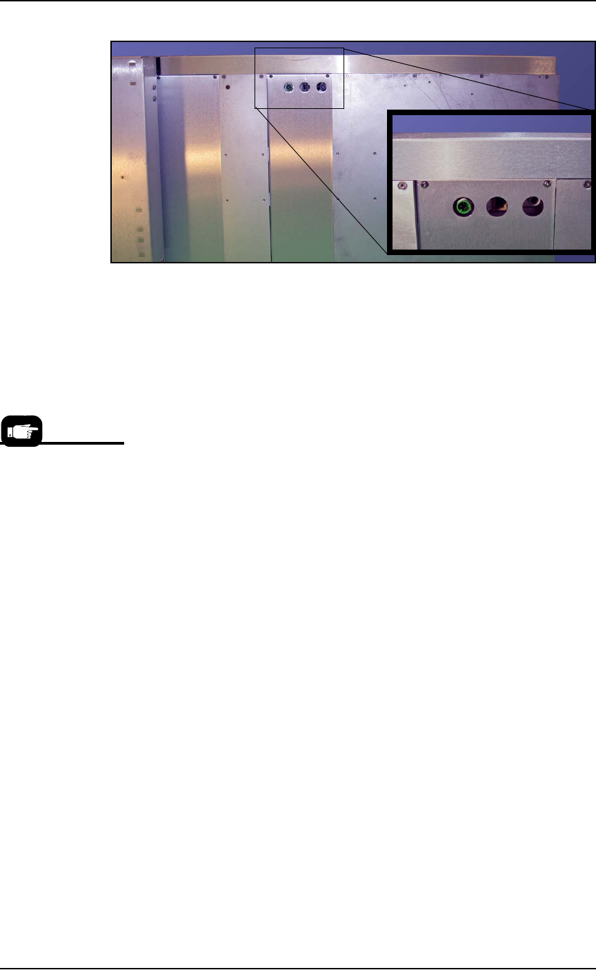
Figure 2-11: Connection for the Data I/O Dual Tray Feeder: electrical,
Ethernet, and air (left to right).
12. Re-attach the utilities cover.
Very basic operating instructions are covered in the PSV7000 Opera-
tors Manual. Complete instructions are covered in the Data I/O Dual
Tray Feeder Owner’s Manual.
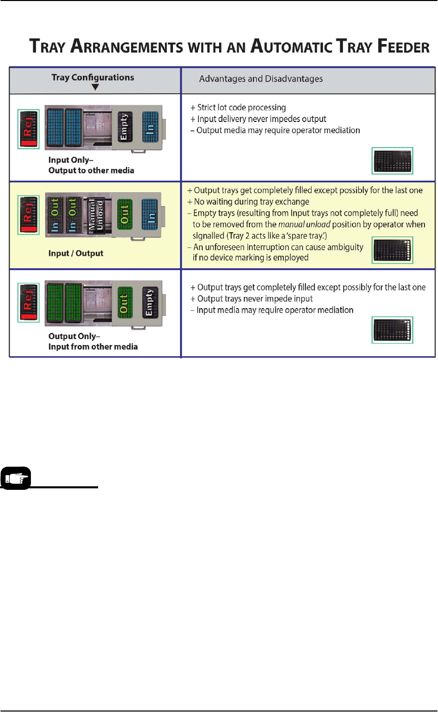
Tray Arrangements
You can use a spare tray with an Automatic Tray Feeder (ATF). When
tray position two is designated as a spare static tray, the devices from
that spare tray are used to replace rejected devices. They are also
used during a tray change.
For possible configurations, see the chart on the following page.
A ‘spare tray’ is also
referred to as an ‘aux-
iliary static tray.’
■ Setting Up Input and Output Media ◘ Setting Up an Automatic Tray Feeder
PSV7000 Owner’s Manual 2—17
back
Figure 2-12: Possible Input/Output layouts with an Automatic Tray
Feeder. A reject bin could be used instead of a tray.
Remember that
•the Setup window > Options tab must be set to match the work-
space setup (covered in the Operator’s Manual).
• The Package File must be taught the location of the Reject con-
tainer (covered in Chapter 3 of this manual).
• (Optional) If the Sort-On-Error-Code is used, two Reject Bins are
required. Set up for Sort-On-Error-Code by installing a second
Reject Bin.
For more about
Sort-On-Error-Code, see
Monitoring Statistics on
page 3-12.
Setup ■ Setting Up Input and Output Media
2—18 Data I/O • 096-0460-001B
back
Figure 2-13: With an Automatic Tray Feeder as Input and a spare tray
as Auxiliary Input, it’s possible to set both trays as input in the
Setup > Options window as shown.
Setting Up the Tube Input and Output
Media
As an option, the PSV7000 System can be configured with Tube Input
and Tube Output Media.
To set up the tube input and tube output media:
1. Shut OFF the PSV7000. See Shutting Down the PSV7000 System on
page 2-7.
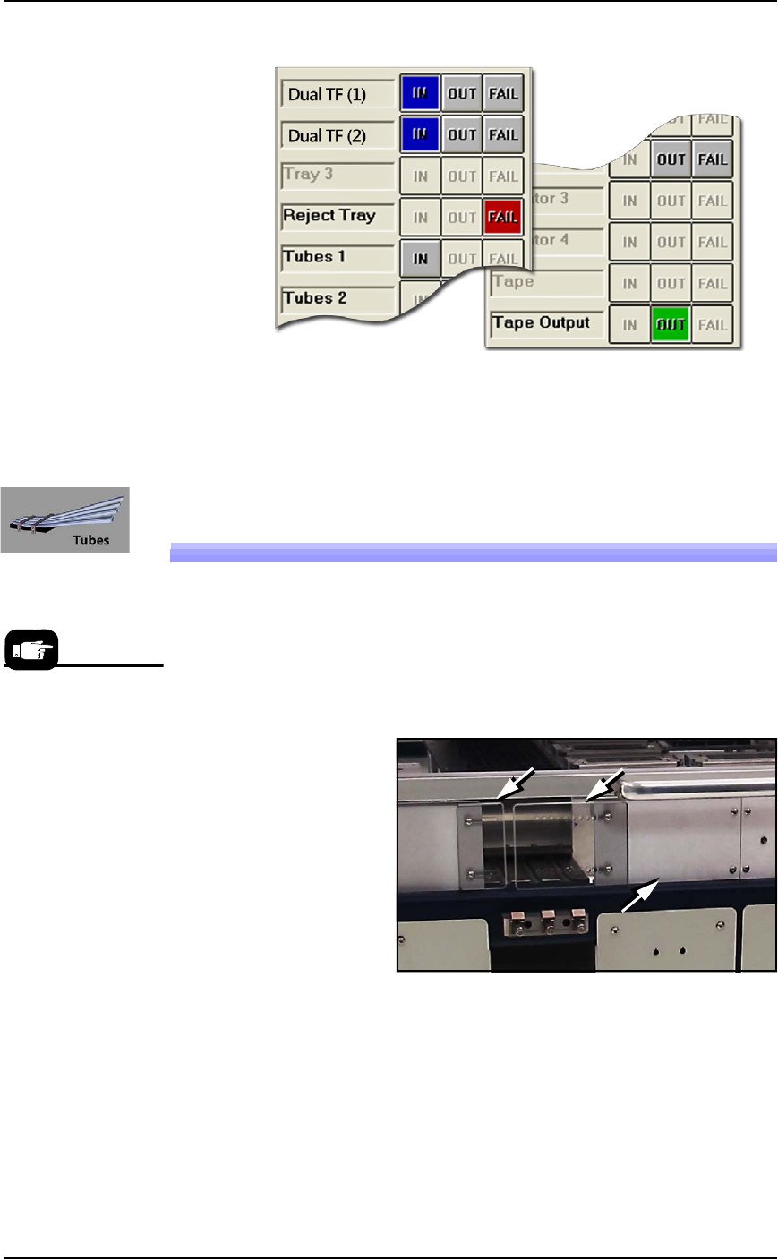
Figure 2-14: Two safety plates and one access plate must be removed
for Tube Vibration System. (Safety plate orientation may vary.)
2. Remove the two screws securing each small safety plate (3 mm
hex key) and remove the plate(s). Refer to the figures above.
3. If Tube Output is also desired, remove the aluminum access
plate adjacent to the feeder mount to install Tube Output media.
4. Align the rail on the bottom of the input vibrator module with
the desired channel on the PSV7000 base plate and slide it
inward. When the feeder reaches the spring latches, lift it over to
Tube Media informa-
tion is subject to
change.