PSV7000_ Owners Manual_096-0460-001B - 第57页
■ Setting Up Input and Output Media ◘ Setting Up the Tube Input and Output Media PSV7000 Owner’s Manual 2—19 back the far side of the latches usin g the handle and push down to secure. Refer to the figures below . Figure…
Setup ■ Setting Up Input and Output Media
2—18 Data I/O • 096-0460-001B
back
Figure 2-13: With an Automatic Tray Feeder as Input and a spare tray
as Auxiliary Input, it’s possible to set both trays as input in the
Setup > Options window as shown.
Setting Up the Tube Input and Output
Media
As an option, the PSV7000 System can be configured with Tube Input
and Tube Output Media.
To set up the tube input and tube output media:
1. Shut OFF the PSV7000. See Shutting Down the PSV7000 System on
page 2-7.
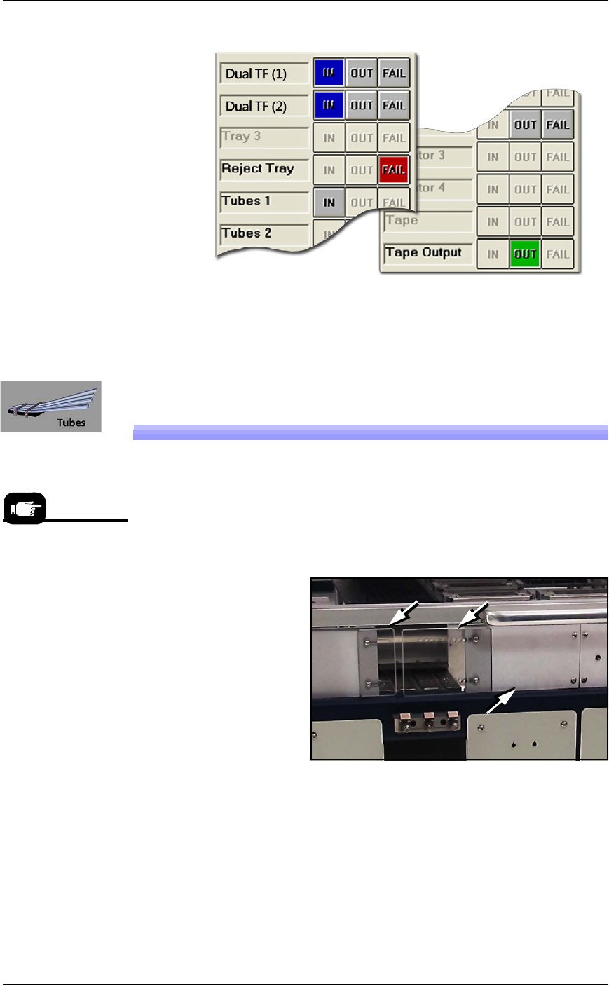
Figure 2-14: Two safety plates and one access plate must be removed
for Tube Vibration System. (Safety plate orientation may vary.)
2. Remove the two screws securing each small safety plate (3 mm
hex key) and remove the plate(s). Refer to the figures above.
3. If Tube Output is also desired, remove the aluminum access
plate adjacent to the feeder mount to install Tube Output media.
4. Align the rail on the bottom of the input vibrator module with
the desired channel on the PSV7000 base plate and slide it
inward. When the feeder reaches the spring latches, lift it over to
Tube Media informa-
tion is subject to
change.
■ Setting Up Input and Output Media ◘ Setting Up the Tube Input and Output Media
PSV7000 Owner’s Manual 2—19
back
the far side of the latches using the handle and push down to
secure. Refer to the figures below.
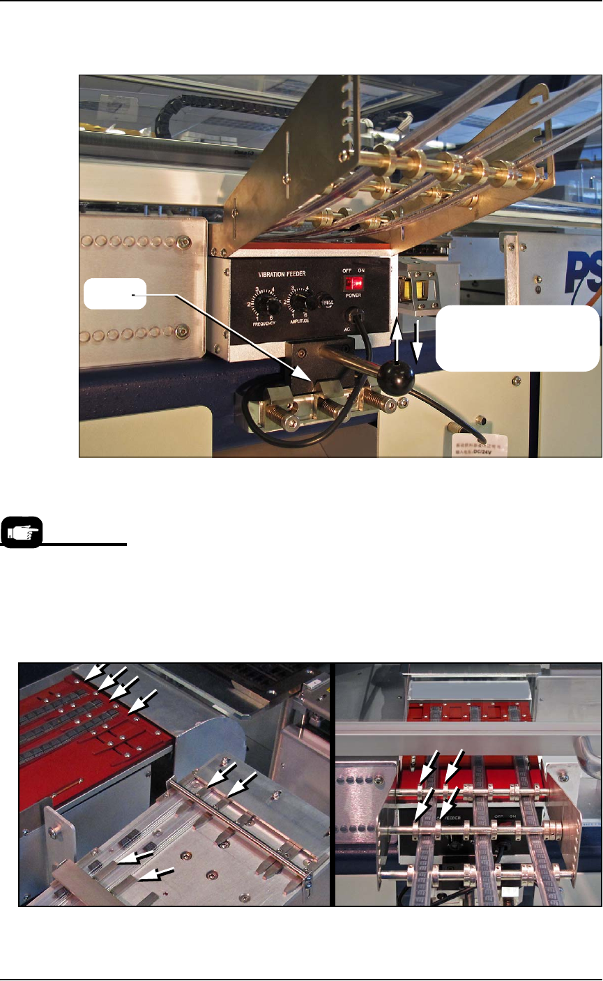
Figure 2-15: Sample Tube Input Module is installed. The Tube Output
module has not yet been installed. If no Tube Output is used, the
access plate must be in place for safety.
5. Insert the communication cable part way into the left socket on
the handler and, while pushing lightly, rotate until the connector
is oriented correctly (it will stop and make a slight click sound
when it goes the rest of the way on).
6. Determine the size of the device tube required.
7. Adjust the flat guide bars and the set-screw collars (guides) to
match the tube locations.
Figure 2-16: Tube input guides.
Latch
Lift over the latch, and
then press down in place
to engage the latch.
To remove the Tube
Feeder communication
cable, grasp the collar
and pull out.
Setup ■ Setting Up Input and Output Media
2—20 Data I/O • 096-0460-001B
back
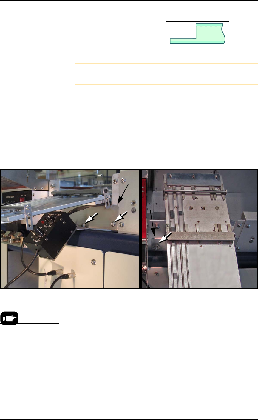
8. Cut a notch in the tube ends slightly longer than the device for
picking and placing devices.
9. Insert tubes into the Tube-In Module.
Note: Stop-plugs help prevent loosing devices until the tubes are in
place.
10. Teach the tube pick and place locations to the Package file.
11. If using Tube Output, install the output tube module.
11a.Install the mounting base with four screws (3 mm hex key)
from underneath the work surface.
11b.Install one Tube-Out front bracket with two fasteners (2 mm
hex key).
11c.Install the vibrator to the mounting base with four screws
(4 mm hex key) and to the front bracket with four screws
(2.5 mm hex key and wrench).
Figure 2-17: Tube Output Module fasteners (white arrows). The
mounting base is not visible in these views. The Tube Out Front Bracket
is indicated with black arrows.
12. Insert the communication cable part way into the right socket on
the handler and, while pushing lightly, rotate until the connector
is oriented correctly (it will stop and make a slight click sound
when it goes the rest of the way on).
13. Restart the PSV7000 System.
14. Edit the winAH400.ini file for tube feeders—
14a.Using Windows Explorer, locate
C:\AH700\winAH400.ini
and m
ake a backup copy, for example,
winAH400backup.ini
.
14b.Open the original file with Microsoft Notepad.
If you have previously
used Tube Feeders you
may already have saved
a winAH400.ini file (with
a temporarily modified
name or in a different
folder) specifically for a
Tube Feeder setup.