PSV7000_ Owners Manual_096-0460-001B - 第59页
■ Setting Up Input and Output Media ◘ Setting Up the Tape Output System PSV7000 Owner’s Manual 2—21 back 14c. Locate the line TubeFeeder1=FALSE and change to TubeFeeder1=TRUE 14d.Locate the line TubeFeeder2=FALSE and cha…
Setup ■ Setting Up Input and Output Media
2—20 Data I/O • 096-0460-001B
back
8. Cut a notch in the tube ends slightly longer than the device for
picking and placing devices.
9. Insert tubes into the Tube-In Module.
Note: Stop-plugs help prevent loosing devices until the tubes are in
place.
10. Teach the tube pick and place locations to the Package file.
11. If using Tube Output, install the output tube module.
11a.Install the mounting base with four screws (3 mm hex key)
from underneath the work surface.
11b.Install one Tube-Out front bracket with two fasteners (2 mm
hex key).
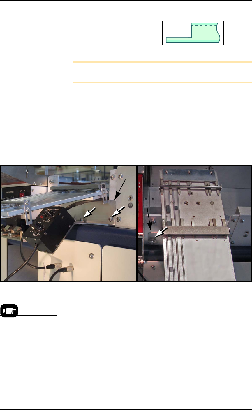
11c.Install the vibrator to the mounting base with four screws
(4 mm hex key) and to the front bracket with four screws
(2.5 mm hex key and wrench).
Figure 2-17: Tube Output Module fasteners (white arrows). The
mounting base is not visible in these views. The Tube Out Front Bracket
is indicated with black arrows.
12. Insert the communication cable part way into the right socket on
the handler and, while pushing lightly, rotate until the connector
is oriented correctly (it will stop and make a slight click sound
when it goes the rest of the way on).
13. Restart the PSV7000 System.
14. Edit the winAH400.ini file for tube feeders—
14a.Using Windows Explorer, locate
C:\AH700\winAH400.ini
and m
ake a backup copy, for example,
winAH400backup.ini
.
14b.Open the original file with Microsoft Notepad.
If you have previously
used Tube Feeders you
may already have saved
a winAH400.ini file (with
a temporarily modified
name or in a different
folder) specifically for a
Tube Feeder setup.

■ Setting Up Input and Output Media ◘ Setting Up the Tape Output System
PSV7000 Owner’s Manual 2—21
back
14c.Locate the line
TubeFeeder1=FALSE
and change to
TubeFeeder1=TRUE
14d.Locate the line
TubeFeeder2=FALSE
and change to
TubeFeeder2=TRUE
14e.Save the winAH400.ini file and exit Windows Explorer.
Running the Tube media is covered in the Operator’s Manual, revi-
sion B and later.
Running Tube Input and Output
1. Insert tubes and adjust tube guides.
Note: Ensure that blank devices are loaded into the input tubes
with the correct pin 1 orientation. If pin 1 orientation doesn’t
match pin 1 on the sockets, the correct rotation much be taught in
the Package file.
Pin 1 on Data I/O sockets is almost always toward the far side of
the adapter (the back of the machine). Some BGAs and PLCCs are
marked.
2. Turn the power switch ON at both the Input vibrator module
and output module.
3. Adjust vibration controls if devices do not travel freely in either
tube.
Remember that:
•The Setup window > Options tab must be set to match the work-
space setup. This is covered in the Operator’s Manual.
• The Package File must be taught the Tube locations.
Setting Up the Tape Output System
The PSV7000 System can be configured with an optional Tape Output
System.
The Tape Output System receives programmed devices directly from
the PSV7000 System via the PNP head. The Tape Output System
advances the carrier tape through a mechanism that seals the tape
(using heat or pressure), and rolls the filled tape onto a reel for
delivery to the next stage in the manufacturing process.
On the Gantry window,
the Tube Feeders are
associated with the yel-
low position labels that
read Vib1 and Vib2.
Setup ■ Setting Up Input and Output Media
2—22 Data I/O • 096-0460-001B
back
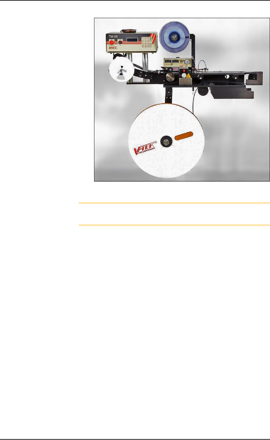
Figure 2-18: Tape Output System.
Note: For additional information, refer to the TM-50 SMD Taping
Module User’s Guide that came with your Tape Output System.
Installing the Tape Output Module onto the
PSV7000 Machine
Tools Required
•metric hex key set
• 10 mm wrench
• two to three people to lift / install the Tape Output Module
These steps are for installing the TM-50 SMD Taping Module (which
can be ordered with the PSV7000).
1. On the left side of the machine prepare the two small clear safety
covers and one sensor for receiving the Tape Out Module.
1a. Loosen three screws that secure an irregular shaped safety
shield (4 mm hex key) and slide it to the right.
1b. Loosen the screw on the lower left of a rectangular safety
shield shown in Figure 2-19 on page 2–23 (4 mm hex key).
1c. Unscrew the top screw (4 mm hex key).
1d. Rotate the rectangular shield ccw 90° and screw it to the
fixed safety shield with the screw you just removed. Refer to
the figure below.