PSV7000_ Owners Manual_096-0460-001B - 第61页
■ Setting Up Input and Output Media ◘ Setting Up the Tape Output System PSV7000 Owner’s Manual 2—23 back Figure 2-19: T o install the T a pe Output Module, shield ‘A ’ slides to the right. Shield ‘B’ rotat es countercl o…
Setup ■ Setting Up Input and Output Media
2—22 Data I/O • 096-0460-001B
back
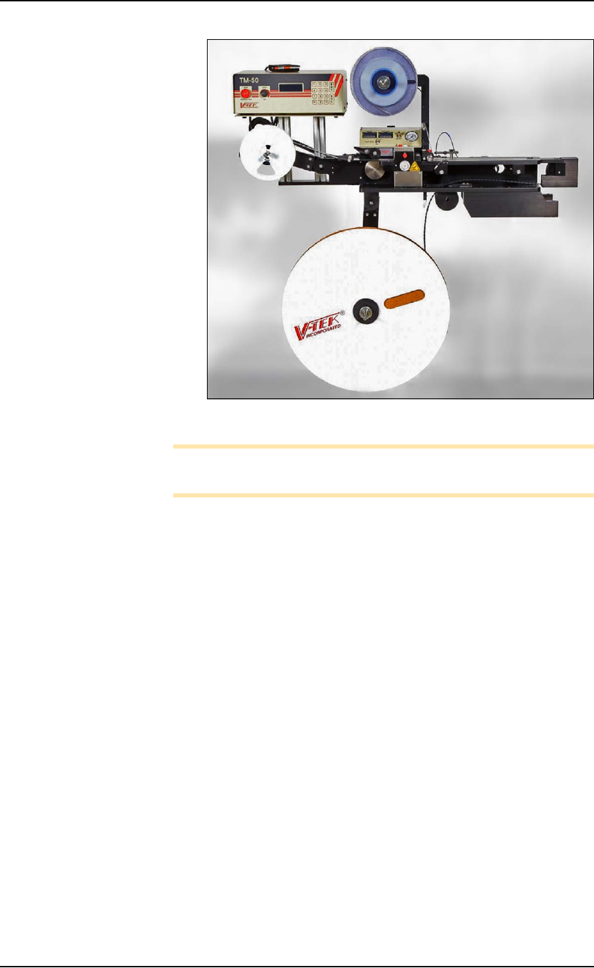
Figure 2-18: Tape Output System.
Note: For additional information, refer to the TM-50 SMD Taping
Module User’s Guide that came with your Tape Output System.
Installing the Tape Output Module onto the
PSV7000 Machine
Tools Required
•metric hex key set
• 10 mm wrench
• two to three people to lift / install the Tape Output Module
These steps are for installing the TM-50 SMD Taping Module (which
can be ordered with the PSV7000).
1. On the left side of the machine prepare the two small clear safety
covers and one sensor for receiving the Tape Out Module.
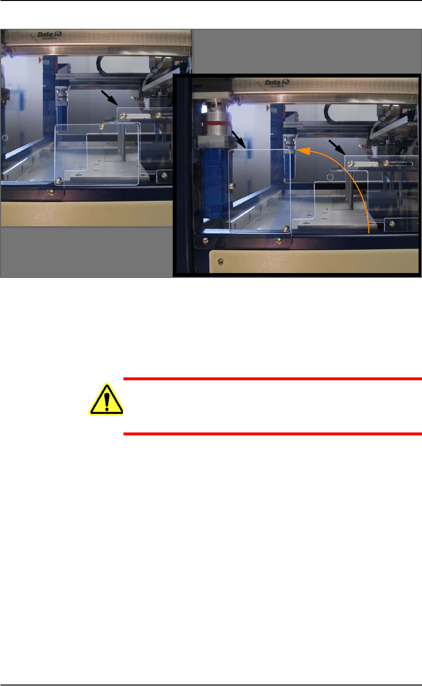
1a. Loosen three screws that secure an irregular shaped safety
shield (4 mm hex key) and slide it to the right.
1b. Loosen the screw on the lower left of a rectangular safety
shield shown in Figure 2-19 on page 2–23 (4 mm hex key).
1c. Unscrew the top screw (4 mm hex key).
1d. Rotate the rectangular shield ccw 90° and screw it to the
fixed safety shield with the screw you just removed. Refer to
the figure below.
■ Setting Up Input and Output Media ◘ Setting Up the Tape Output System
PSV7000 Owner’s Manual 2—23
back
Figure 2-19: To install the Tape Output Module, shield ‘A’ slides to the
right. Shield ‘B’ rotates counterclockwise 90°.
1e. Unscrew the two screws that secure the safety shield sensor
(2.5 mm hex key) and let the sensor hang.
1f. Unscrew the five screws that secure large fixed safety shield
(4 mm hex key).
WARNING: Possible injury or property damage! The Tape
Output Module is heavy. Use caution. Two people are
required to lift this equipment. Approximate weight: 47.63 kg
(105 lbs.). A third person may be required to bolt it into place.
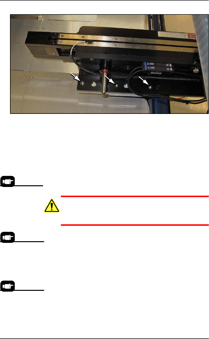
2. Install the Tape Output Module onto the plate in the PSV7000
workspace and screw it down with six screws (4 mm hex key).
See Figure 2-20.
A
B
A
Setup ■ Setting Up Input and Output Media
2—24 Data I/O • 096-0460-001B
back
Figure 2-20: TM-50 Tape-Output Module mounting screws. Three more
locations on opposite side (hidden in this view). Viewed from the back
of the machine.
3. Reinstall the large fixed safety shield with five screws.
4. Reinstall the sensor onto the shield.
5. Re-adjust the irregular shaped safety shield. To fill the gaps, this
shield will require adjustment to accommodate the position of
the track (table) once it is set to the desired track/tape width.
Setting Up the Tape Output Module
CAUTION: Possible tape damage from Excessive Heat! Improper
routing of the device tape may cause enough heat to melt the
tape. Ensure the correct routing path is followed. See the TM-50
SMD Taping Module User’s Guide.
To set up the Tape Output System:
1. Edit the winAH400.ini file for Tape Output—
1a. Using Windows Explorer, locate
C:\AH700\winAH400.ini
and m
ake a backup copy, for example,
winAH400backup.ini
.
1b. Open the original file with Microsoft Notepad.
1c. Locate the line:
TapeOutPutInstalled=FALSE
and change it to True:
TapeOutputInstalled=TRUE
1d. Save the
winAH400.ini
file and exit Windows Explorer.
The information that
follows is adapted
from the TM-50 SMD
Taping Module User’s
Guide that came with
your Tape Output Sys-
tem.
If you have previously
used Tape Output, you
may already have
saved a winAH400.ini
file specifically for a
Tape Output setup.
The communication
cable may also be
called I/O or Sensor
Output.