PSV7000_ Owners Manual_096-0460-001B - 第95页
■ Marking Options ◘ (Optional) Creating a Laser Marking File PSV7000 Owner’s Manual 3—25 back V erifying Proper Laser Operation WA R NI N G: P o ss ib l e h e a lt h ha z ar d f r o m t o xi c fu m e s! La s e r m ar k -…
Administrative Functions ■ Marking Options
3—24 Data I/O • 096-0460-001B
back
Marking Options
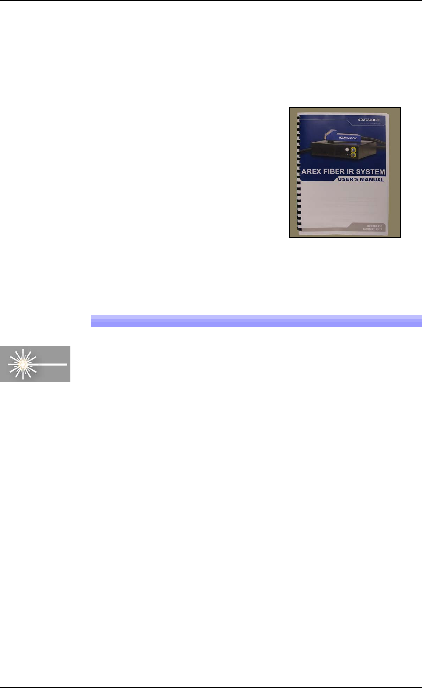
A laser Laser Module is an option which marks the surface of the
devices. It has a separate Operation Manual which came with your
PSV7000 System if it has the option.
Figure 3-11: Manual for the laser device marker.
(Optional) Creating a Laser Marking File
Laser graphics used to mark devices are generated using the Lighter
Editor software included with the Laser Option. It resides in the
Laser Computer. Any style of marking (whether text-based,
graphic-based, or both) can be generated and used for marking
devices. The only limitation is the size of the device to be marked.
For instructions creating an image file for the Laser System, see the
AH700 on-screen Help topic Setting up and Teaching > Create a Laser
Marking File.
Laser
■ Marking Options ◘ (Optional) Creating a Laser Marking File
PSV7000 Owner’s Manual 3—25
back
Verifying Proper Laser Operation
WARNING: Possible health hazard from toxic fumes! Laser mark-
ing generates vapors, fumes, and particles that can be noxious,
toxic, or even fatal. Follow maintenance procedures. Use proper
ventilation.
Requirements
• An image file is in the Lighter Editor SW application.
To verify that the laser is marking as expected:
1. At the Run window, click RunOne.
Only one device will be processed.
2. Verify that the marking graphic placement on the device is as
desired. If not, adjust the laser file in the Lighter application or
see the next heading on troubleshooting.
Aligning Laser Marking
Requirements
•Two people
• An image file is in the Lighter Editor SW application.
If the device is not marked, check that the laser is aimed at the device
correctly:
1. Stop any job that is running by clicking Finish on the Run win-
dow.
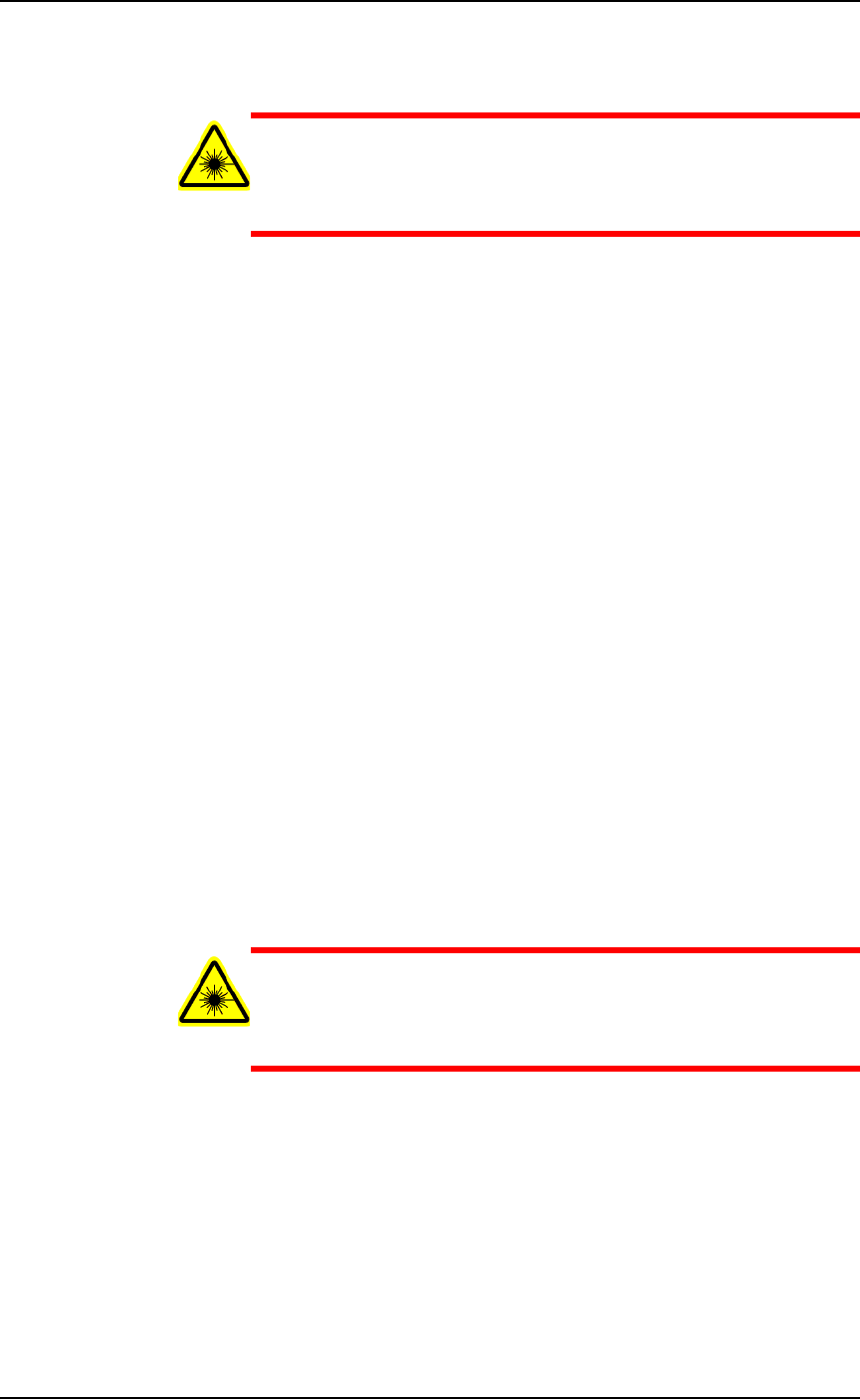
2. Turn the Laser PC Enable Selector OFF. (The Key Selector should
be ON.)
WARNING: Serious injury hazard to eyes and skin! Do not open
or work on the Laser Module when the Enable Selector is in the
ON position. Always make sure it is OFF. The two lamps on the
back of the Laser Module must be green.
Administrative Functions ■ Marking Options
3—26 Data I/O • 096-0460-001B
back
Figure 3-12: The Laser PC Enable Selector (arrow) and the Key
Selector.
3. Switch to the Laser PC by pressing the Scroll Lock (ScrLk) key-
board key twice and then number 2.
4. If the Lighter SW Engine is open, close it.
5. Navigate to your laser art file on the Laser PC:
D:\Data\docs\layouts\
. Files have a .xlp extension. Dou-
ble-click your file to open it in the Lighter Editor SW.
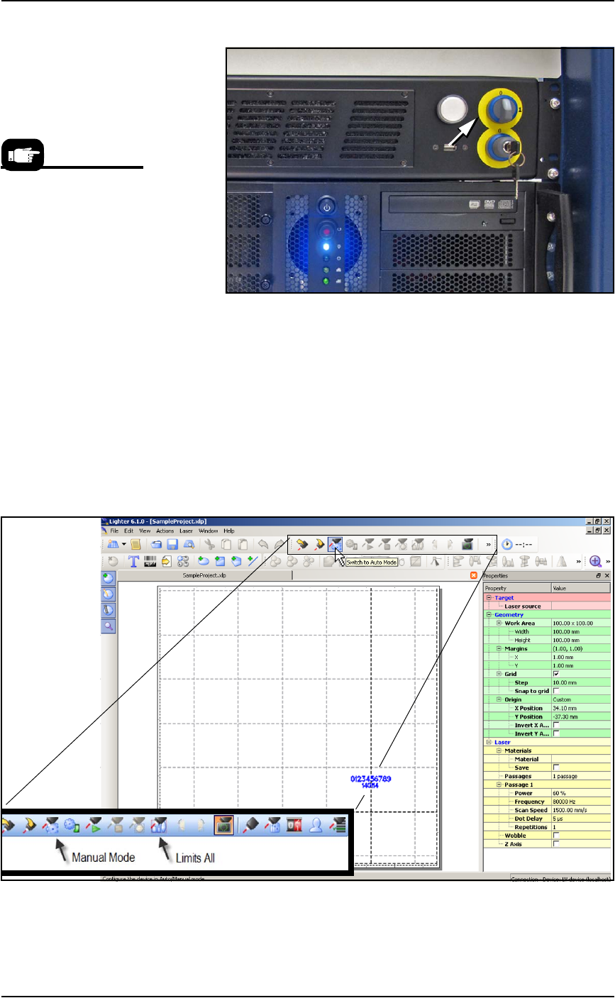
6. Click Switch to Manual Mode. The Limits All button becomes
available.
Figure 3-13: The Manual Mode button enables the Limits All button.
7. Click Limits All to turn on a low power laser target light.
The Laser is warmed up
when you see a tooltip in
lower right corner of the
Windows tray.