PSV7000_ Owners Manual_096-0460-001B - 第96页
Administrative Functions ■ Marking Options 3—26 Data I/O • 096-0460-001B back Figure 3-12: The Laser PC Enable Selector (arro w) and the K ey Selector . 3. Switch to the Laser PC by pressing the Scroll Lock (ScrLk) key- …
■ Marking Options ◘ (Optional) Creating a Laser Marking File
PSV7000 Owner’s Manual 3—25
back
Verifying Proper Laser Operation
WARNING: Possible health hazard from toxic fumes! Laser mark-
ing generates vapors, fumes, and particles that can be noxious,
toxic, or even fatal. Follow maintenance procedures. Use proper
ventilation.
Requirements
• An image file is in the Lighter Editor SW application.
To verify that the laser is marking as expected:
1. At the Run window, click RunOne.
Only one device will be processed.
2. Verify that the marking graphic placement on the device is as
desired. If not, adjust the laser file in the Lighter application or
see the next heading on troubleshooting.
Aligning Laser Marking
Requirements
•Two people
• An image file is in the Lighter Editor SW application.
If the device is not marked, check that the laser is aimed at the device
correctly:
1. Stop any job that is running by clicking Finish on the Run win-
dow.
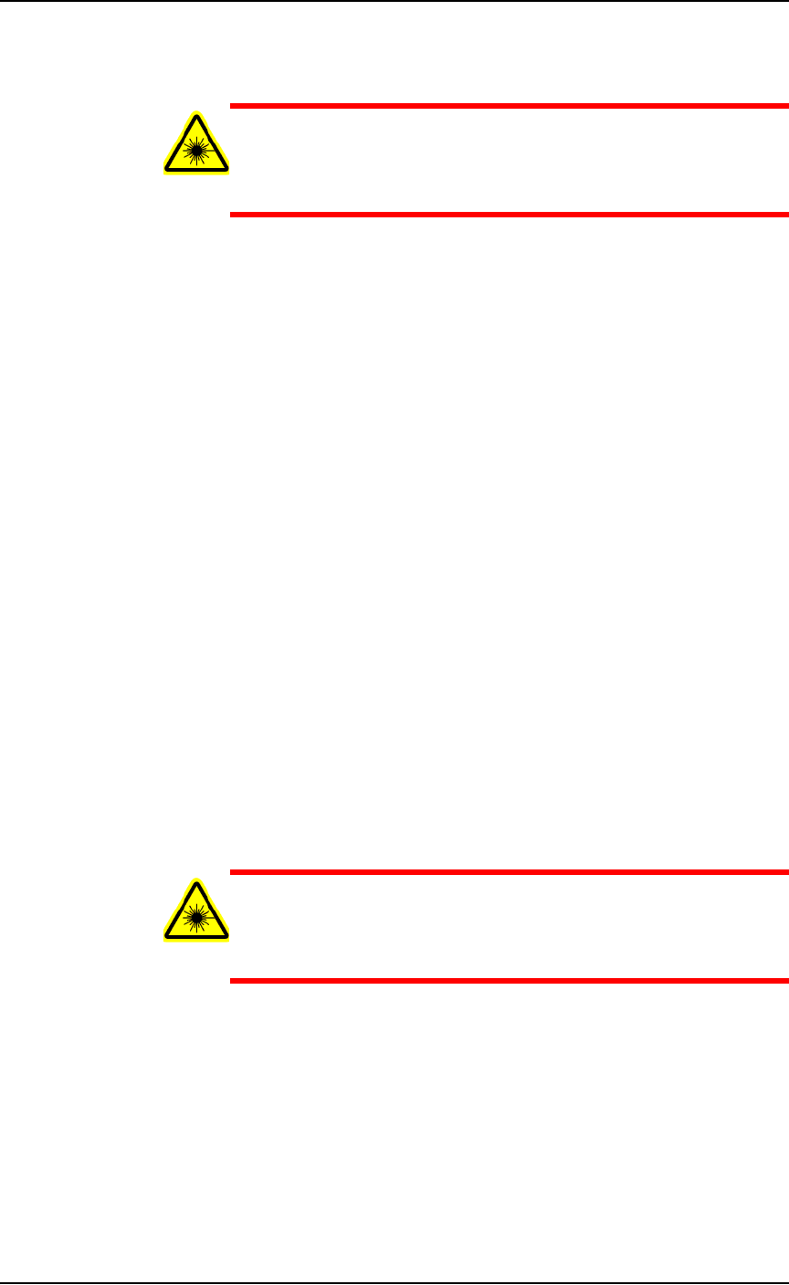
2. Turn the Laser PC Enable Selector OFF. (The Key Selector should
be ON.)
WARNING: Serious injury hazard to eyes and skin! Do not open
or work on the Laser Module when the Enable Selector is in the
ON position. Always make sure it is OFF. The two lamps on the
back of the Laser Module must be green.
Administrative Functions ■ Marking Options
3—26 Data I/O • 096-0460-001B
back
Figure 3-12: The Laser PC Enable Selector (arrow) and the Key
Selector.
3. Switch to the Laser PC by pressing the Scroll Lock (ScrLk) key-
board key twice and then number 2.
4. If the Lighter SW Engine is open, close it.
5. Navigate to your laser art file on the Laser PC:
D:\Data\docs\layouts\
. Files have a .xlp extension. Dou-
ble-click your file to open it in the Lighter Editor SW.
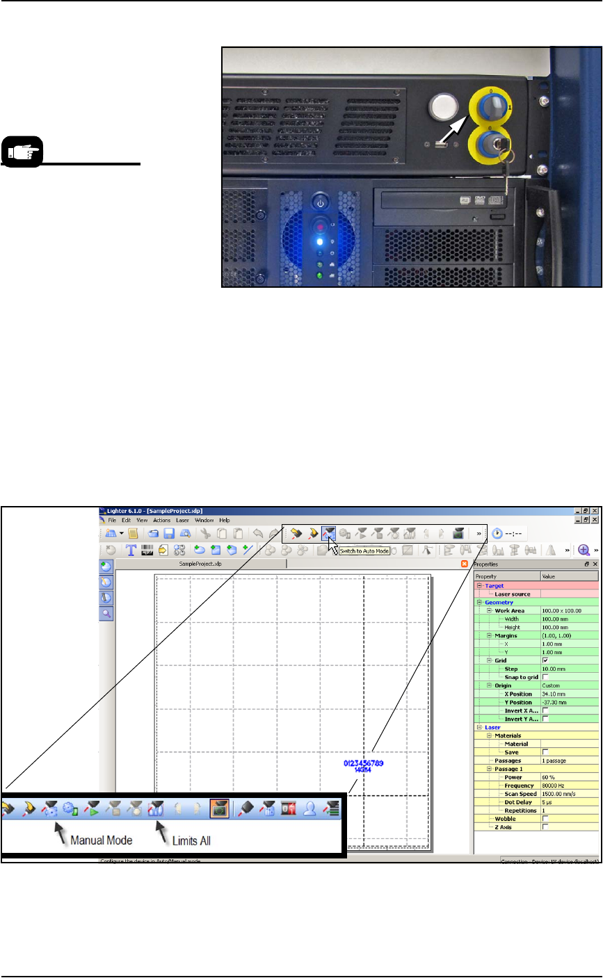
6. Click Switch to Manual Mode. The Limits All button becomes
available.
Figure 3-13: The Manual Mode button enables the Limits All button.
7. Click Limits All to turn on a low power laser target light.
The Laser is warmed up
when you see a tooltip in
lower right corner of the
Windows tray.
■ Marking Options ◘ (Optional) Creating a Laser Marking File
PSV7000 Owner’s Manual 3—27
back
8. Have operator #2 open the PSV7000 rear safety door and
unscrew the knurled screw on the inspection door of the Laser
Module.
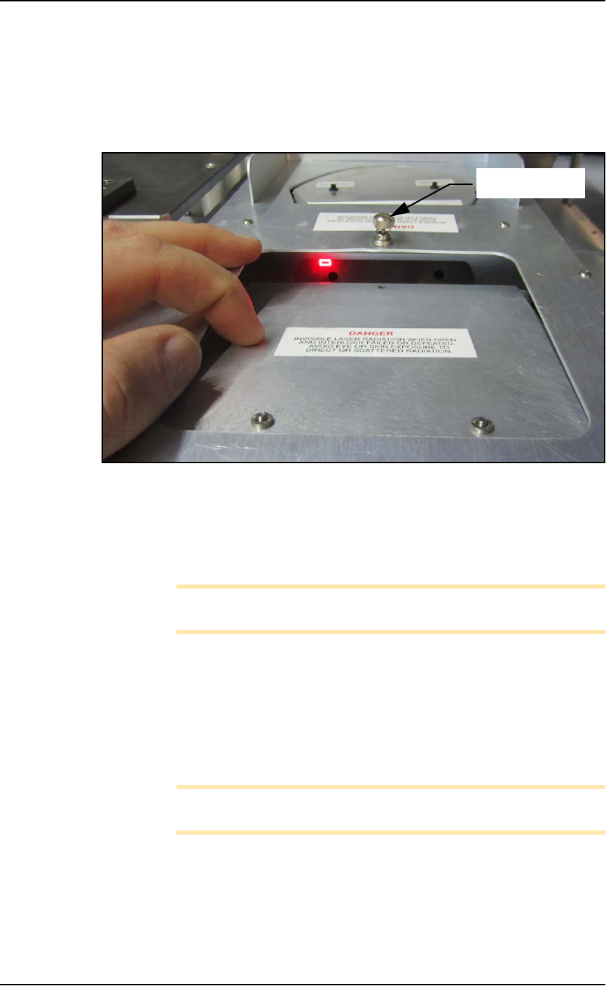
9. Push the hinged inspection door down (open) about just enough
(about 20 mm ) to see the red laser light striking the rotor. See
the figure below.
Figure 3-14: The laser is missing the target in this photo. Only this left
target position must be aligned.
10. If the laser light is not centered on the device tip, then select the
art to be marked and drag it as directed by operator #2.
Zoom in for ease of use.
Note: The actual target laser light moves in the opposite direction
of art movement in the Lighter Editor.
11. When satisfied, Save your changes.
12. Close the inspection door and tighten the knob.
13. Retry Running One device. Refer to the previous heading.
If all appears correct and still there is no mark, contact Data I/O Cus-
tomer Support.
Note: The Laser rotor has been leveled at the factory. If you experi-
ence trouble, contact Data I/O Customer Support.
Knurled screw