PSV7000_ Owners Manual_096-0460-001B - 第99页
■ 3D Coplanarity Option ◘ Running a Job with 3D Inspection PSV7000 Owner’s Manual 3—29 back 2. T oggle the monitor connection to the 3D Insp ection PC by press- ing keyboard Scroll Lock key twice, an d then press 2 or 3 …
Administrative Functions ■ 3D Coplanarity Option
3—28 Data I/O • 096-0460-001B
back
3D Coplanarity Option
The 3D Coplanarity Inspection System should already have the cor-
rect prism Reticle installed. If it has been changed or altered, refer to
the UltraVim User Manual or contact Data I/O.
Requirements
• UltraVim Scanner Technologies Accessories Case (all equipment
required is in this case)
• UltraVim Software User Manual
• TaskLink Ver 7.5 or higher
• The 3D Coplanarity Inspection System should already have the
correct prism Reticle installed. If it has been changed or altered,
refer to the UltraVim User Manual or contact Data I/O.
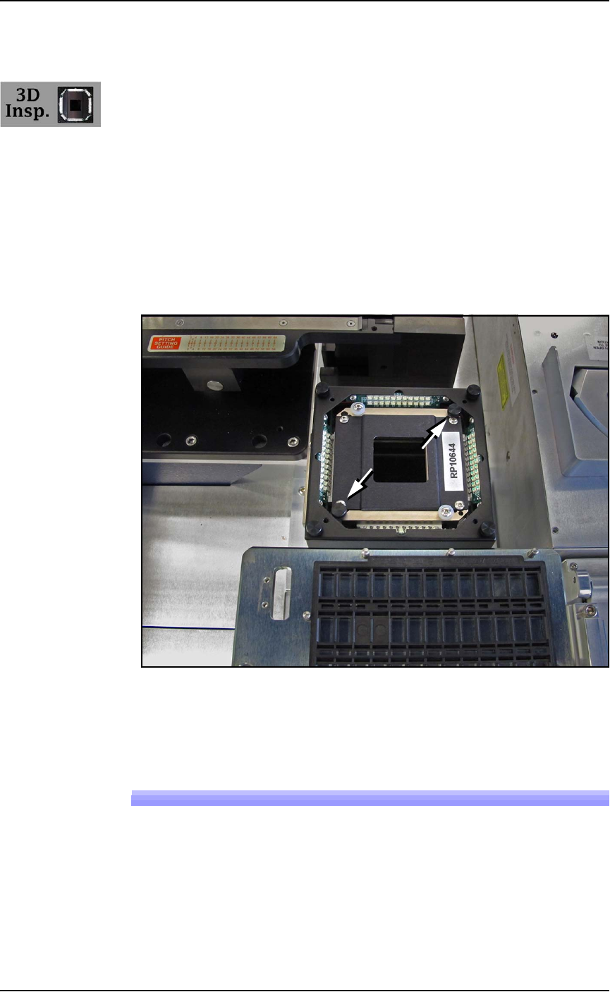
Figure 3-15: Top view with Prism Reticle installed. (Reticle fasteners at
arrows). Ref: also visible in this view are the Laser Module Option and
the Tape-Out Option.
Running a Job with 3D Inspection
1. Start the 3D Inspection PC as follows:
1a. The 3D Inspection PC is just below the Handler PC. Open
the PC door with the key and push the Power switch ON
and release.
1b. Close and lock the door.
■ 3D Coplanarity Option ◘ Running a Job with 3D Inspection
PSV7000 Owner’s Manual 3—29
back
2. Toggle the monitor connection to the 3D Inspection PC by press-
ing keyboard Scroll Lock key twice, and then press 2 or 3 imme-
diately (depending on the number of options installed).
Note: NOTE: When viewing the 3D Inspection PC, use the key-
board and touch-pad. The PSV7000 touchscreen monitor will not
register touches.
3. Open the UltraVim application (double-clicking the desktop
icon).
4. A file for your device type is required. There are three choices to
accomplish this:
A) Use an existing file in the UltraVim Package Library,
B) Copy, paste, and rename an existing file, or
C) Create a new file.
File extensions are:
Note: There is also a *.MRK file for Mark & Package inspection.
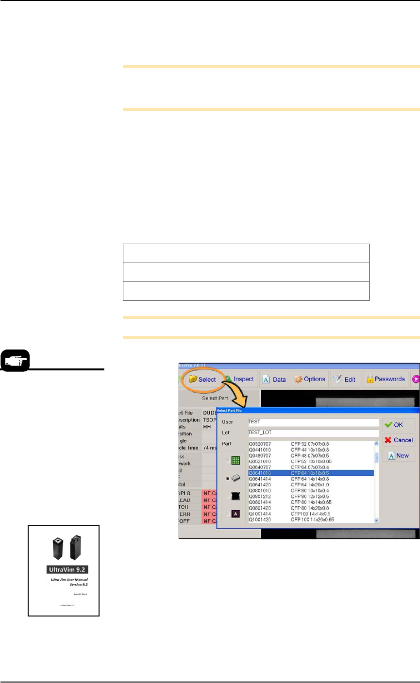
Figure 3-16: In the UltraVim application, clicking Select (circled) opens
the 'Package' library. This window may be password protected. See the
UltraVim User Manual for Help.
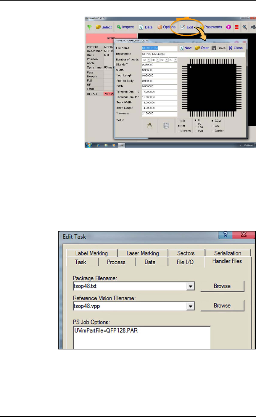
To create a new device file, or edit an existing one, click Edit and
enter data from the device specifications.
*.BGA Ball Grid Array
*.PAR Gull Wing and J-Lead
*.LCC QFN and LCC
When creating your job in
TaskLink, you may want to
check the UltraVim Package
Library to ensure that your
target package is available.
1. Open the UltraVim
Application.
2. Click Select.
3. View library
Refer to the UltraVim
User Manual for instruc-
tions.
Administrative Functions ■ 3D Coplanarity Option
3—30 Data I/O • 096-0460-001B
back
Figure 3-17: Adding or editing a device specifications file.
5. On the PSV7000 keyboard, push the monitor toggle sequence to
switch back to the PS Handler computer (scroll lock key twice
and then 1).
6. For the desired job in TaskLink, open the Edit Task dialog > Han-
dler Files tab. In the PS Job Options field, type in the name of the
device file you created; (the UltraVim manual terminology is
part file). These files are stored on the 3D Inspection System
computer.
Figure 3-18: : The PS Job Options field (TaskLink > Edit Task >
Handler Files) is an editor that you type into directly which passes
parameters to the AH700 Software.
7. Save the job.